
Fan power generation system with function of storing gravitational potential energy and control method thereof

A technology of gravitational potential energy and fan power generation, applied in the field of wind power generation, can solve problems such as complex systems, inability to release energy at the same time, and huge initial investment

Pending Publication Date: 2018-11-16
秦明
View PDF7 Cites 7 Cited by
  • Summary
  • Abstract
  • Description
  • Claims
  • Application Information

AI Technical Summary

Problems solved by technology

[0004] 1. Unbalanced wind energy, solar energy and other green energy cannot be converted and stored;
[0005] 2. The initial investment is huge, the construction period is long, and the construction volume is large;
[0006] 3. Far away from the load center, additional power transmission and transformation equipment is required;
[0007] 4. The system is complex, there are many equipments, and the technical requirements are high;
[0008] 5. It requires specific geological and hydrological conditions and covers a large area;
[0009] 6. Huge impact on the local natural ecological environment;
[0010] 7. During the process of energy storage, energy cannot be released to generate electricity at the same time

Method used


Image

  • Fan power generation system with function of storing gravitational potential energy and control method thereof
  • Fan power generation system with function of storing gravitational potential energy and control method thereof
  • Fan power generation system with function of storing gravitational potential energy and control method thereof

Examples


Embodiment approach

[0041] 1. Wind Tower

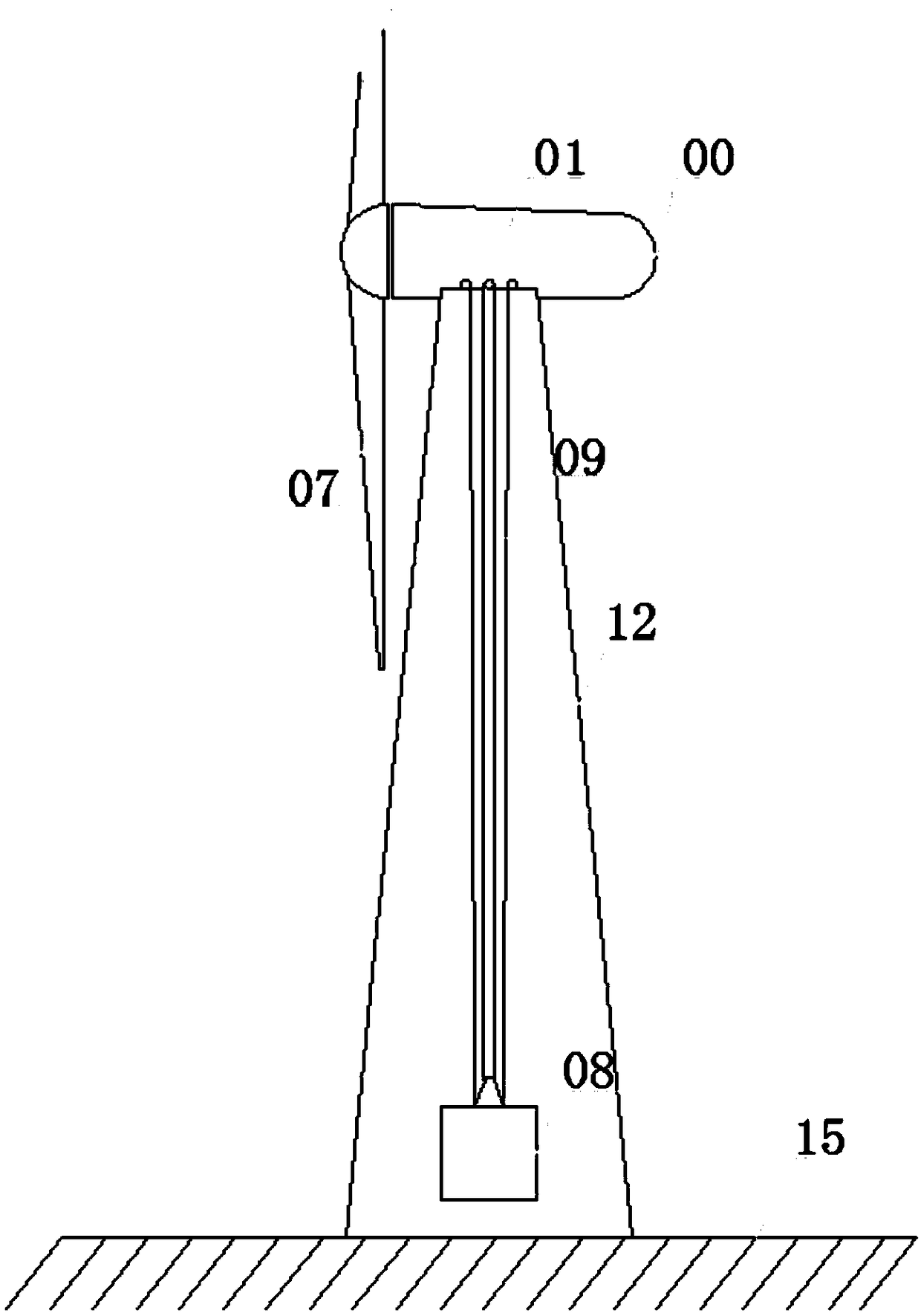
[0042] All mechanical components are installed in or on the top of the wind energy tower 12, and the gravity body 08 only runs vertically up and down in the wind energy tower 12 tower body to perform energy conversion, collection and storage, and energy release for power generation.

[0043] 2. Well tower type

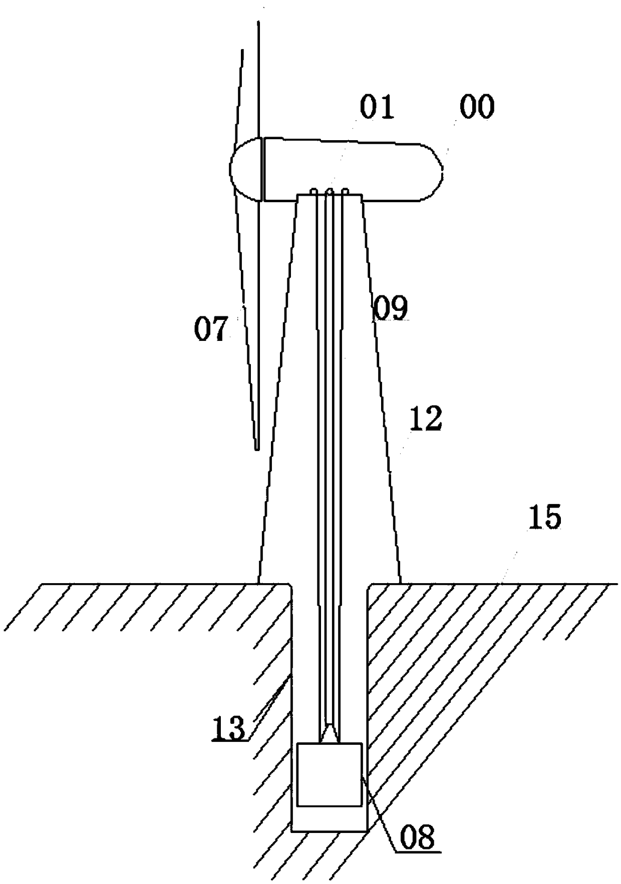
[0044] All mechanical components are installed in the inside or top of the wind energy tower 12, and the gravity body 08 is in the underground shaft 13 (this shaft 13 can be manually excavated as required or reasonably utilized in conjunction with the original geological conditions) and the wind energy tower 12 towers The body runs vertically up and down to transform energy, collect and store it, and release energy to generate electricity. The combination of ground and underground can effectively increase the lifting distance of the gravity body 08, so that the total power of energy storage and the time of continuous power generation can be bett...


PUM


Abstract

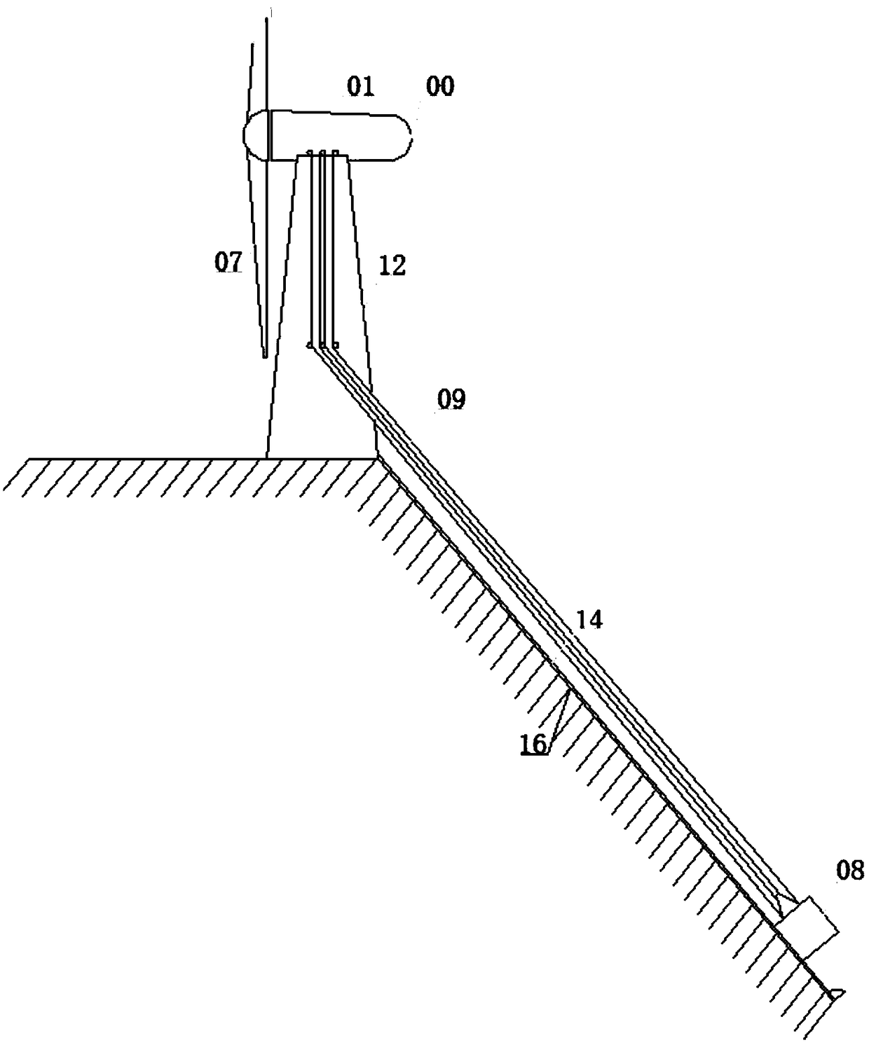
The invention discloses a fan power generation system with the function of storing gravitational potential energy. A wind energy tower is installed on the ground, a fan cabin is installed at the top of the wind energy tower, a wind energy shaft is fixed in the fan cabin, the wind energy shaft is connected with fan blades outside the fan cabin, the wind energy shaft is connected with the input endof a wind power conversion clutch machine, and the two output ends of the wind power conversion clutch machine are connected with a one-way transmission shaft F and a one-way transmission shaft C respectively. The fan power generation system has the advantages that the kinetic energy of wind can be collected by using the wind blades, meanwhile, the residual electric energy obtained at the load peak of an electric power system or the electric energy obtained through other modes are converted into mechanical kinetic energy, wherein a gravity body is lifted to the upper end of the wind energy tower or the relatively high position of other structural bodies, so that the wind energy or electric energy which cannot be stored is converted into the gravitational potential energy which can be stored of the gravity body, and the fan power generation system is provided with a wind power storage gravitational potential energy power generation system which can realize synchronous operation of energy storage and power generation.

Description

technical field [0001] The invention relates to the field of wind power generation, in particular to a wind power storage gravitational potential energy generation system capable of synchronous operation of energy storage and power generation. Background technique [0002] There are always peaks and troughs in the use of electric energy. Often, the supply of electric energy is insufficient during the peak period, and there is excess electric energy during the trough period. None of the existing power generation methods can avoid such problems. Although it can be dispatched through the power grid, it is inevitable to waste energy in new energy power generation by abandoning wind, light, and electricity. Green energy such as wind energy and solar energy are greatly affected by meteorological conditions and cannot provide a continuous source of power. There may not be wind or sun during peak power consumption. Moreover, in traditional wind power generation, the power grid can...

Claims


Application Information

Patent Timeline
IPC IPC(8): F03D9/16
CPCF03D9/16Y02E10/72Y02E60/16Y02E70/30
Inventor 秦明
Owner 秦明
Learn More