
Electronic gear stage switching method, device and vehicle

A gear switching, electronic technology, applied in transmission control, components with teeth, belts/chains/gears, etc. Touch phenomenon, avoid confusion effect

Active Publication Date: 2018-11-16
SHANGHAI KOSTAL HUAYANG AUTOMOTIVE ELECTRIC +1
View PDF9 Cites 1 Cited by
  • Summary
  • Abstract
  • Description
  • Claims
  • Application Information

AI Technical Summary

Problems solved by technology

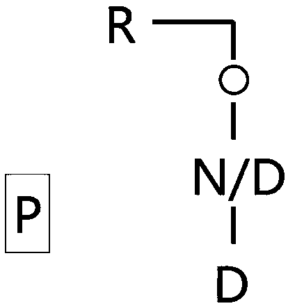
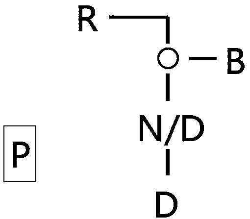
Traditional vehicle gearboxes include at least four basic gears of P / R / N / D, and may also include other gears such as M gear and S gear. Each gear corresponds to a position, and the four basic gears are pressed by P / The order of R / N / D is arranged. When parking, put the gear lever in the P position. When starting the vehicle, you need to pull the gear lever from the P gear to the R and N gears in order to mount the D gear. The vehicle moves forward and stops. When shifting the gear lever from D gear to P gear in the reverse direction, since the gear position is fixed, the angle of movement needs to be relatively large during operation, which occupies a large volume of the center console; the driver frequently switches gears at large angles, which is likely to cause confusion. It is necessary to use the instrument panel to prompt the current gear, which brings trouble to the driver's operation
[0003] The existing in-line electronic shifter needs to set an unlock button on the operating handle, and the gear must be pressed to switch gears, which is used to prevent the driver from accidentally pulling the gear lever to the R gear during normal driving. , to prevent the vehicle from being damaged by accidentally engaging the reverse gear when moving forward; the driver needs to find the position of the button and press it first, and the operation process is not smooth

Method used


Image

  • Electronic gear stage switching method, device and vehicle
  • Electronic gear stage switching method, device and vehicle
  • Electronic gear stage switching method, device and vehicle

Examples


Embodiment Construction

[0055] The core of the present invention is to provide an electronic gear switching method, which can realize the function of preventing accidental touch without setting the unlocking button and ensure the safety of use.

[0056] In order to enable those skilled in the art to better understand the technical solutions of the present invention, the electronic gear switching method, device and automobile of the present invention will be described in detail below with reference to the drawings and specific implementations.

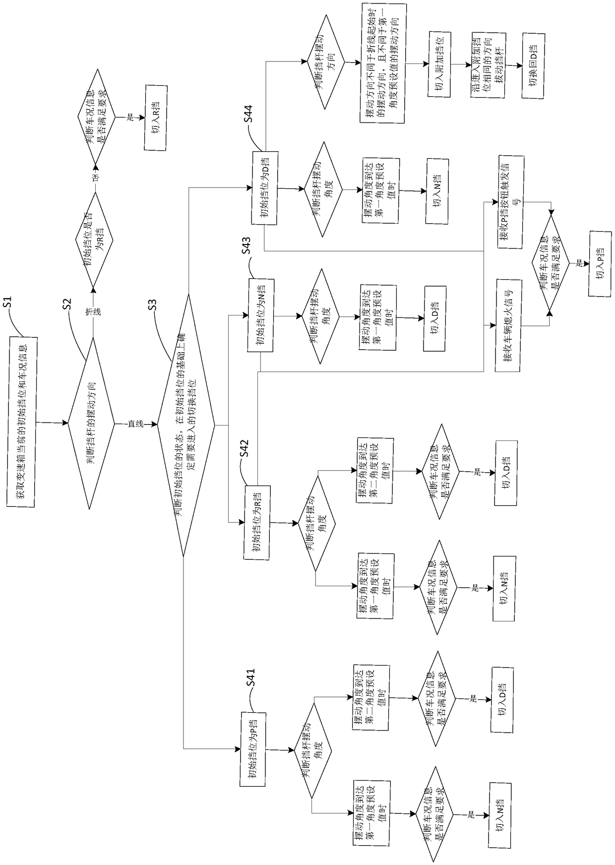
[0057] The invention provides an electronic gear switching method, such as figure 1 Shown is the flow chart of the method; it is used for the gear lever that can be automatically reset, that is, the elastic reset structure is set at the gear lever. When the gear lever is not stressed, it can be automatically reset. The driver applies force to the gear lever to make The blocking lever swings in different directions, the method includes the following steps:

[0058] S1...


PUM


Abstract

The invention discloses an electronic gear stage switching method. The current initial gear stage of a transmission and vehicle information are acquired; the swinging parameter of a gear lever is acquired; the swinging direction of the gear lever is judged; if the swinging direction is a broken line, whether the initial gear stage is at an R stage or not is judged; if not, whether braking vehicleinformation meets requirement or not is judged, if yes, the gear stage is switched to the R stage; if the swinging direction is linear, the state of the initial gear stage is judged; and a switching gear stage needs to be switched to is determined on the basis of the initial gear stage. According to the electronic gear stage switching method, the switching process of the R stage is divided into two combination movements in different directions, namely the gear stage cannot be switched to the R stage by only translating in one direction; and the gear stage can be switched to the R stage normally only when the gear lever is operated manually to do broken-line combination movements and the vehicle requirement meets the requirement. At other gear stages, the R stage can be switched to throughthe same operation; the gear lever does not need to be swung in large angle, so that the situation that a driver gets confused when switching the gear stage. The invention further discloses an electronic gear stage switching device and vehicle, and the same technical effect can be realized.

Description

Technical field [0001] The present invention relates to the technical field of transmissions, and further relates to an electronic gear shifting method. In addition, the invention also provides an electronic gear switching device and an automobile. Background technique [0002] The gearbox is a mechanism that changes the speed and torque from the engine. It can change the transmission ratio of the output shaft and the input shaft fixedly or in stages, and expand the role of the torque and speed of the driving wheels. The traditional vehicle gearbox includes at least four basic gears, P / R / N / D, and can also include other gears such as M gear and S gear. Each gear corresponds to a position. The four basic gears are in accordance with P / The sequence of R / N / D is arranged. When parking, the gear lever is placed in the P gear position. When starting the vehicle forward, you need to pull the gear lever from the P gear and pass through the R and N gears to the D gear. The vehicle moves ...

Claims


Application Information

Patent Timeline
Patent Type & Authority Applications(China)
IPC IPC(8): F16H59/10F16H59/38F16H61/02
CPCF16H59/105F16H59/38F16H61/0202F16H61/0204F16H2306/00
Inventor 姜宁进李鹃
Owner SHANGHAI KOSTAL HUAYANG AUTOMOTIVE ELECTRIC
Learn More