Elastic sealing flange

A technology of elastic sealing and flange, which is applied in the direction of flange connection, pipe/pipe joint/pipe fitting, passing components, etc., can solve the problem of poor continuity of flange sealing effect, shorten the distance between the fixed plate and the upper coil, and make it difficult to repeat Use and other problems to achieve a good coating protection effect

Inactive Publication Date: 2018-11-16
无锡市钰汌工贸有限公司
View PDF0 Cites 0 Cited by
  • Summary
  • Abstract
  • Description
  • Claims
  • Application Information

AI Technical Summary

Problems solved by technology

[0005] Aiming at the problems in the prior art, the present invention provides an elastic sealing flange, which solves the problem that the existing flange has poor sealing effect and is difficult to reuse. Through the setting of the spring column and the positioning screw, the fixed disk can be shortened. The distance from the upper coil to achieve the effect of continuous tight sealing

Method used


Image

  • Elastic sealing flange
  • Elastic sealing flange

Examples


Embodiment Construction

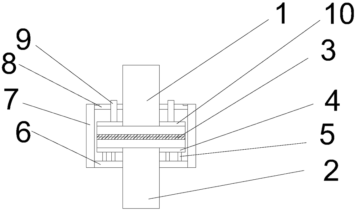
[0016] combine figure 1 and figure 2 , which describes a specific embodiment of the present invention in detail, but does not limit the claims of the present invention in any way.

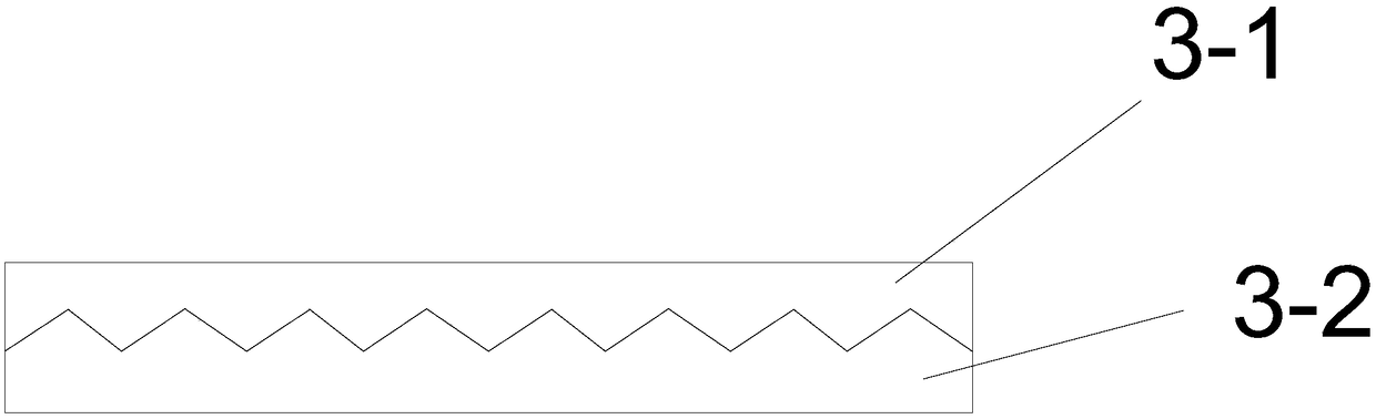
[0017] Such as figure 1 and figure 2 As shown, an elastic sealing flange includes an upper tube coil 1 and a lower tube coil 2, the upper tube coil 1 and the lower tube coil 2 are connected correspondingly, and a rubber is arranged between the upper tube coil 1 and the lower tube coil 2 Pad 3, the bottom of the lower tube plate 2 is provided with a supporting tray 4, the lower surface of the supporting tray 4 is connected with several vertically arranged spring columns 5, and the bottom tube of the spring column 5 is fixed with a fixed plate 6, so The fixed disk 6 is fixed with a sleeve 7 by screws, and the outer peripheral surface of the fixed disk 6 is connected with the lower nozzle of the sleeve 7, and the upper nozzle of the sleeve 7 is connected with a positioning disk 7 by a screw, and ...


PUM


Abstract

The invention belongs to the technical field of flanges, and in particular, relates to an elastic sealing flange. The elastic sealing flange comprises an upper pipe disc and a lower pipe disc; the upper pipe disc is correspondingly connected with the lower pipe disc; a rubber pad is arranged between the upper pipe disc and the lower pipe disc; a support disc is arranged at the bottom of the lowerpipe disc; the lower surface of the support disc is connected with multiple spring columns vertically arranged; fixed discs are fixed on bottom pipes of the spring columns; the fixed discs are fixed with sleeves through screws; the outer peripheral surfaces of the fixed disc are connected with lower pipe orifices of the sleeves; upper pipe orifices of the sleeves are connected with positioning discs through screws; the positioning discs are positioned rightly above the upper pipe disc; multiple positioning holes are formed in the upper surface of the positioning discs; and positioning screw rods are arranged in the positioning holes. The elastic sealing flange solves the problems of bad sealing effect continuity and difficult recycling of a traditional flange; and through arrangement of the spring columns and the positioning screw rods, the gaps from the fixed discs to the upper pipe disc can be shortened to achieve continuous pressing and sealing effect.

Description

technical field [0001] The invention belongs to the technical field of flanges, and in particular relates to an elastic sealing flange. Background technique [0002] In the known technical field, the flange sealing structure usually consists of a pair of flanges, a sealing ring and several sets of fasteners. The sealing ring is placed in the sealing groove of the flange. After the fasteners are tightened, the sealing ring is The force deforms and fills the space of the sealing groove, so that the contact surface of the flange is sealed without leakage. This flange sealing structure only uses one sealing ring for sealing. Once the sealing ring is damaged due to factors such as internal medium corrosion and thermal environment, the flange structure will leak. [0003] A flange structure using double-channel metal sealing rings invented by Sheng Xuanyu et al. has been greatly improved compared with the above-mentioned flange structure using single-channel sealing rings. The re...

Claims


Application Information

Patent Timeline
Patent Type & Authority Applications(China)
IPC IPC(8): F16L23/032F16L23/22
CPCF16L23/032F16L23/22
Inventor 刘学庆
Owner 无锡市钰汌工贸有限公司
Why Eureka
Try Eureka