
Thin-film magnetic head, head gimbal assembly with thin-film magnetic head and magnetic disk apparatus with head gimbal assembly

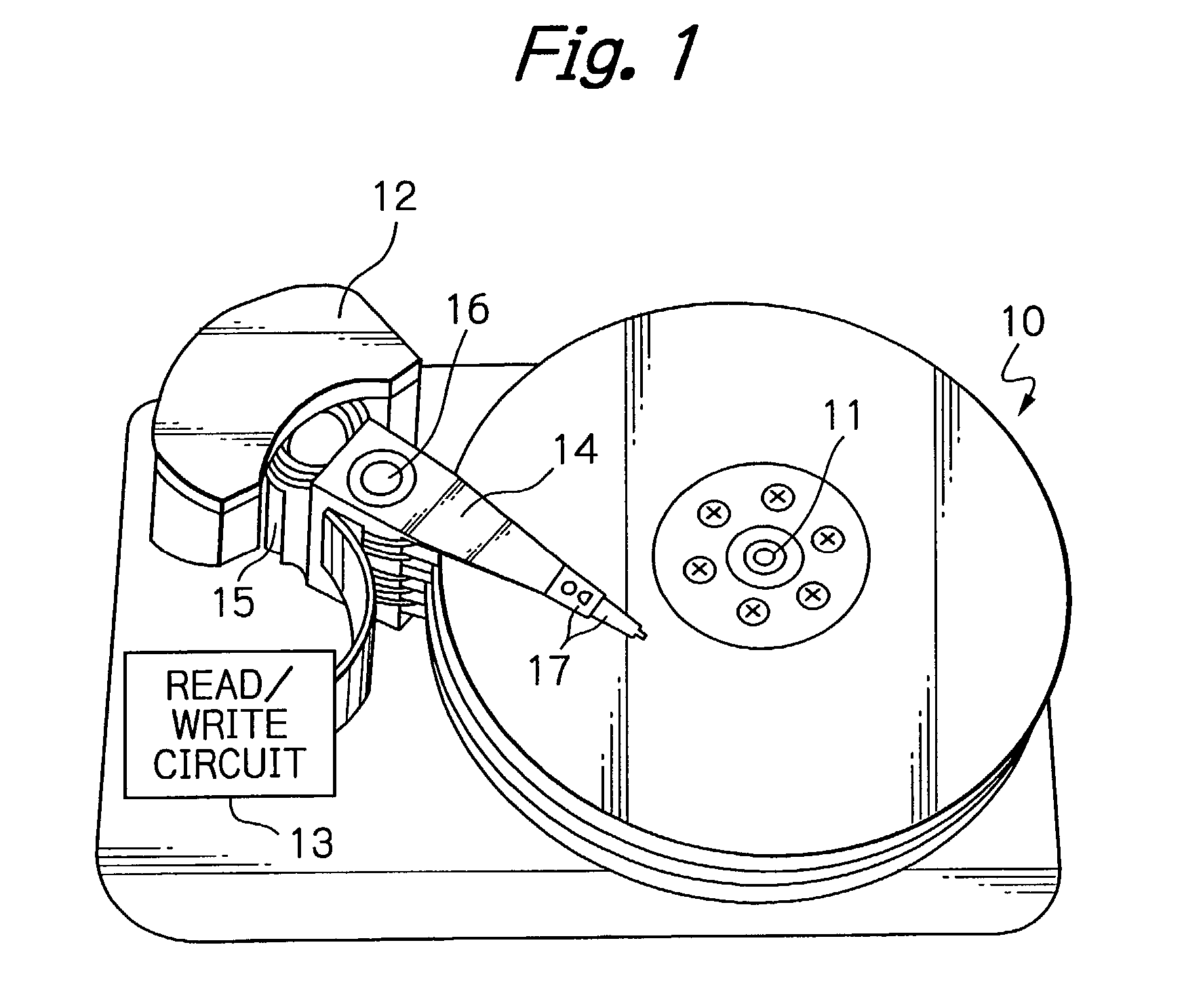
a thin-film magnetic head and head gimbal technology, which is applied in the direction of maintaining the head carrier alignment, recording information storage, instruments, etc., can solve the problems of increasing the possibility of collision between the magnetic head slider and the surface of the magnetic disk, requiring a very complicated assembling process, and reducing the variation of the magnetic spacing between thin-film magnetic heads. , the effect of small magnetic spacing

Active Publication Date: 2006-06-27
TDK CORPARATION
View PDF24 Cites 61 Cited by
  • Summary
  • Abstract
  • Description
  • Claims
  • Application Information

AI Technical Summary

Benefits of technology

[0008]It is therefore an object of the present invention to provide a thin-film magnetic head, an HGA with the thin-film magnetic head and a magnetic disk apparatus with the HGA, whereby a small magnetic spacing can be attained and also variations of the magnetic spacing among thin-film magnetic heads can be reduced.
[0009]Another object of the present invention is to provide a thin-film magnetic head, an HGA with the thin-film magnetic head and a magnetic disk apparatus with the HGA, whereby a small magnetic spacing can be attained and also the magnetic spacing can be more precisely controlled.

Problems solved by technology

However, if a flying height of the magnetic head slider is lowered to make the magnetic spacing small, the probability of occurrence of collision between the magnetic head slider and the surface of the magnetic disk increases.
This collision may cause a breakage of the magnetic head slider.
Such known method however requires a very complicated assembling process for additionally attaching a discrete piezoelectric element to the magnetic head slider.
In addition, according to such known method, it is difficult to precisely keep a constant flying height among a plurality of magnetic head sliders because the flying height of each slider will differ from others due to manufacturing variations occurred during the assembling.
Integral manufacturing of the piezoelectric element mainly made of a sintered ceramic and the magnetic head slider is impossible due to the difference in their process temperatures.

Method used


Image

  • Thin-film magnetic head, head gimbal assembly with thin-film magnetic head and magnetic disk apparatus with head gimbal assembly
  • Thin-film magnetic head, head gimbal assembly with thin-film magnetic head and magnetic disk apparatus with head gimbal assembly
  • Thin-film magnetic head, head gimbal assembly with thin-film magnetic head and magnetic disk apparatus with head gimbal assembly

Examples


fourth embodiment

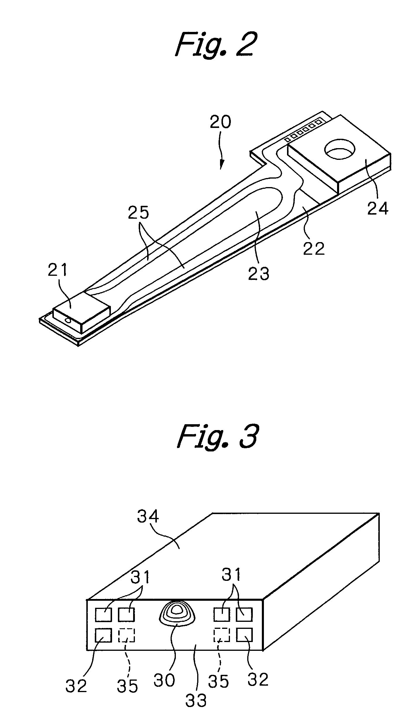
[0065]As shown in FIG. 3, the magnetic head slider in this embodiment has, on its element-forming surface 33, a magnetic write head element and a magnetic read head element 30 laminated each other, four signal electrode terminals 31 electrically connected to these elements and two heating current electrode terminals 32 electrically connected to a heater (not shown in FIG. 3). In this figure, reference numeral 34 denotes an ABS of the magnetic head slider and 35 indicated in a broken line denotes another two heating current electrode terminals in case of the fourth embodiment having two heaters.

first embodiment

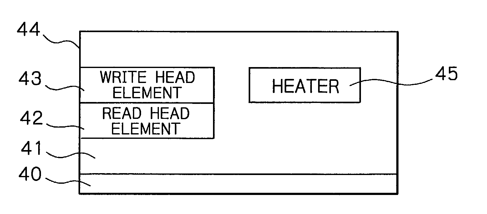
[0066]FIG. 4 schematically illustrates a configuration of the magnetic head slider or the thin-film magnetic head in this

[0067]As shown in this figure, the thin-film magnetic head in this embodiment has a substrate 40, an insulation layer 41 formed on the substrate 40, the magnetic read head element 42 and the magnetic write head element 43 sequentially laminated on the insulation layer 41, and the heater 45 formed at a position opposite to the ABS 44 with respect to the write head element 43. The heater 45 operates to jut or protrude end sections of the read and / or write head elements from the ABS due to its thermal expansion.

[0068]In this embodiment, the heater 45 is laminated at substantially the same level or height as that of the write head element 43 in order to simplify manufacturing processes. However, the lamination height of the heater according to the present invention is not limited to that in this embodiment. Namely, the heater 45 may be laminated at substantially the s...

second embodiment

[0087]FIG. 11 schematically illustrates a configuration of the magnetic head slider or the thin-film magnetic head in a second embodiment according to the present invention.

[0088]As shown in this figure, the thin-film magnetic head in this embodiment has a substrate 110, an insulation layer 111 formed on the substrate 110, a flexible layer 116 formed on the insulation layer 111, and a magnetic read head element 112 and a magnetic write head element 113 sequentially laminated. A heater 115 is formed at a position opposite to the ABS with respect to the write head element 113. The heater 115 operates to jut or protrude end sections of the read and / or write head elements from the ABS due to its thermal expansion. The flexible layer 116 functions to smooth the movement of the magnetic head elements due to the thermal expansion.

[0089]In this embodiment, the heater 115 is laminated at substantially the same level or height as that of the write head element 113 in order to simplify manufac...


PUM

PropertyMeasurementUnit
flexibleaaaaaaaaaa
magneticaaaaaaaaaa
currentaaaaaaaaaa

Abstract

A thin-film magnetic head includes at least one thin-film magnetic head element with an ABS, and at least one heating means located at a position opposite to the ABS with respect to the at least one thin-film magnetic head element. The at least one heating means is energized to heat at least when the at least one thin-film magnetic head element operates.

Description

FIELD OF THE INVENTION[0001]The present invention relates to a thin-film magnetic head, to a head gimbal assembly (HGA) with the thin-film magnetic head and to a magnetic disk apparatus with the HGA.DESCRIPTION OF THE RELATED ART[0002]In such magnetic disk apparatus, a thin-film magnetic head element for writing magnetic information into and / or reading magnetic information from a magnetic disk is in general formed on a magnetic head slider flying in operation above a rotating magnetic disk. The slider is fixed at a top end section of a suspension of the HGA.[0003]Recently, track width of a thin-film magnetic head rapidly becomes narrower to satisfy the requirement forever increasing data storage capacities and densities in today's magnetic disk apparatus. If the track width becomes narrow, signal recording ability in a magnetic write head element to the magnetic disk will decrease and signal-reproducing ability in a magnetic read head element from the magnetic disk will also decreas...

Claims


Application Information

Patent Timeline
Patent Type & Authority Patents(United States)
IPC IPC(8): G11B5/127G11B5/31G11B5/39G11B5/48G11B5/60G11B21/21
CPCG11B5/6064G11B5/60G11B5/4853G11B5/3103G11B5/607
Inventor KAMIJIMA, AKIFUMI
Owner TDK CORPARATION
Learn More