Measuring method and system of optical axis center and angle of view of camera movement

A measurement method and camera technology, applied in the field of cameras, can solve problems such as complex workload of offset data

Inactive Publication Date: 2018-11-16
GOSUNCN TECH GRP
View PDF1 Cites 13 Cited by
  • Summary
  • Abstract
  • Description
  • Claims
  • Application Information

AI Technical Summary

Problems solved by technology

[0008] In view of this, the present invention proposes a method and system for measuring the center of the optical axis of the camera core and the angle of view, which solves the complexities caused by manually or semi-automatically measuring a large number of data of the angle of view and the center of the optical axis in the prior art. Workload Technical Issues

Method used


Image

  • Measuring method and system of optical axis center and angle of view of camera movement
  • Measuring method and system of optical axis center and angle of view of camera movement
  • Measuring method and system of optical axis center and angle of view of camera movement

Examples


Embodiment 1

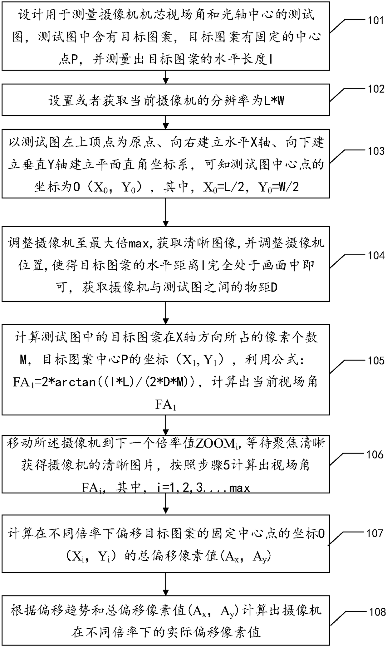
[0076] figure 1 It is a schematic flow chart of this embodiment, a method for measuring the field of view angle of a camera movement and the center of an optical axis, comprising:

[0077] Step 101, designing a test chart for measuring the field of view angle of the camera movement and the center of the optical axis, the test chart contains a target pattern, the target pattern has a fixed center point P, and the horizontal length l of the target pattern is measured;

[0078] It should be noted that in order to solve the data of simultaneously measuring the field of view and optical axis offset, it is necessary to design the test chart reasonably. In this embodiment, the principle of measuring the angle of view is to use the original resolution of the test chart and the known distance (horizontal length l of the target pattern) and the target pattern of the pixel value in the test chart to calculate the actual horizontal direction of the entire picture of the camera in proporti...

Embodiment 2

[0141] Figure 5 It is a schematic diagram of the structure of this embodiment, a measurement system for the angle of view of the camera movement and the center of the optical axis, including:

[0142] The measurement preparation unit 201 is used to establish and obtain data for measuring the field of view angle of the camera movement and the center of the optical axis;

[0143] An angle of view measuring unit 202, used to measure the angle of view of the camera movement;

[0144] The optical axis center measuring unit 203 is used for measuring the offset of the optical axis center of the camera movement.

Embodiment 3

[0146] Image 6 It is a schematic diagram of the structure of this embodiment, a measuring device for the angle of view of the camera core and the center of the optical axis, including:

[0147] The measurement preparation unit 301 is used to establish and obtain data for measuring the field of view angle of the camera movement and the center of the optical axis;

[0148] The test chart design module 3011 is used to design a test chart for measuring the field of view angle of the camera movement and the center of the optical axis, the test chart contains a target pattern, the target pattern has a fixed center point P, and the target pattern is measured The horizontal length l;

[0149] A resolution acquisition module 3012, configured to set or acquire the resolution of the current camera as L*W;

[0150] The coordinate system establishment module 3013 is used to set up the horizontal X axis with the upper left vertex of the test chart as the origin, establish the horizontal ...


PUM


Abstract

The invention provides a measuring method of an angle of view and an optical axis center of a camera movement. A test pattern for measuring the angle of view and the optical axis center of the cameramovement is designed, and the test pattern includes a target image of a fixed center. By means of the resolution of the test pattern, the corresponding pixel value of the target pattern, and the object distance between the camera and the test pattern, the angle of view of the current magnification is calculated by a trigonometric function, and the coordinate set of the fixed center of the target pattern is calculated at different magnifications based on the angle of view; the deviation trend of the optical axis center is calculated by comparing the total deviation value of the coordinate set with respect to the center of the test pattern, and the deviation of the optical axis center of the camera is further calculated according to the trend. The invention can simultaneously measure the angle of view and the deviation of the optical axis, does not need to repeat measurement, and saves time; the pattern alignment is automatically completed; the pattern alignment precision does not need to be too high, as long as the test pattern exists in each picture under each magnification, the data is corrected by the calculation method of the optical axis deviation correction.

Description

technical field [0001] The invention relates to the field of cameras, in particular to a method and system for measuring the optical axis center and field angle of a camera. Background technique [0002] The field of view refers to the angle formed by taking the lens of the optical instrument (camera) as the vertex, and the maximum range of the measured object image to be imaged on the image sensor through the lens. The field of view is different under different magnifications. Generally speaking, the larger the magnification, the stronger the magnification ability, and the smaller the picture, the smaller the field of view. The trend of this field of view varies with the magnification. It will change, so you only need to select some special magnifications for testing, and then calculate the field of view angle at the intermediate continuous magnification according to the difference or fitting method. When a lens with a zoom function performs a zoom operation, the center of...

Claims


Application Information

Patent Timeline
Patent Type & Authority Applications(China)
IPC IPC(8): H04N17/00
CPCH04N17/002
Inventor 张腾腾刘祥涛俞翔黄仝宇汪刚宋一兵侯玉清刘双广
Owner GOSUNCN TECH GRP
Why Eureka
Try Eureka