Explosion-proof cabinet high in security coefficient

A safety factor, explosion-proof cabinet technology, applied in the field of explosion-proof cabinets, can solve the problems of low safety factor, single structure, increased loss, etc., and achieve the effect of high degree of intelligent automation, improved safety factor, and improved locking strength.

Inactive Publication Date: 2018-11-20
李志强
View PDF0 Cites 5 Cited by
  • Summary
  • Abstract
  • Description
  • Claims
  • Application Information

AI Technical Summary

Problems solved by technology

[0003] However, there are still some deficiencies in the existing explosion-proof cabinets. On the one hand, the structure is single, and inflammable and explosive products cannot be flexibly placed in partitions, and it is inconvenient to take and place. When an explosion

Method used


Image

  • Explosion-proof cabinet high in security coefficient
  • Explosion-proof cabinet high in security coefficient
  • Explosion-proof cabinet high in security coefficient

Examples


Embodiment 1

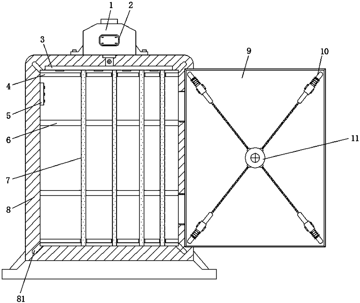
[0026] Example one, reference figure 1 with Figure 5 , An explosion-proof cabinet with a high safety factor, including a cabinet body 8 and a cabinet door 9. The inner surface walls of the cabinet body 8 are equidistantly arranged with multiple layers 6 from top to bottom, and the front sides of the multiple layers 6 A fixed rod 7 is vertically arranged, and the vertical end of the rear surface wall of the fixed rod 7 is welded with multiple partitions 17 at equal intervals. The upper and lower sides of the cabinet body 8 are welded with sliding rods 4 along the horizontal ends. The partitions 17 at the upper and lower ends of the plate 17 are slidably connected to the sliding rod 4, and the spacing between the two partitions 17 is equal to the thickness of the side plate 9. Through the sliding action of the partition 17 on the sliding rod 4, The items can be placed in zones according to the nature and size of the items. On the one hand, the items can be placed more organized a...

Embodiment 2

[0027] Example two, reference figure 1 with Figure 4 , The horizontal end of the top inner surface wall of the cabinet body 8 is fixedly connected with a horizontal pipe 3, and the top center of the horizontal pipe 3 communicates with the fire extinguisher 1 fixed on the top outer surface wall of the cabinet body 8 through the main pipe 16. The fire extinguisher 1 is provided with AVR The central control processor 2, the bottom of the horizontal pipe 3 is equidistantly arranged with a plurality of nozzles 31 along the horizontal end, the cabinet 8 is provided with a temperature sensor 5, the temperature sensor 5 is used to monitor the internal temperature of the cabinet 8 in real time, the main pipeline 16 A solenoid valve 161 is provided on the upper part. The output terminal of the temperature sensor 5 is electrically connected to the input terminal of the AVR central control processor 2, and the output terminal of the AVR central control processor 2 is electrically connected ...

Embodiment 3

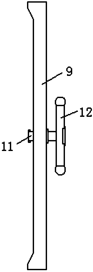
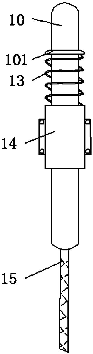
[0028] Example three, reference Figure 1-3 , The front end of one side of the cabinet body 8 is movably connected with a cabinet door 9 through a hinge. The four right angles of the rear surface of the cabinet door 9 are welded with a limit sleeve 14, and the orientation of the limit sleeve 14 faces the right angle of the cabinet door 9. The setting of the limit sleeve 14 can limit the lateral displacement of the limit bolt 10 to avoid position deflection during the movement. The inside of the limit sleeve 14 is sleeved with the limit bolt 10, and the limit bolt 10 is located on the limit pin 10. The outer part of the position sleeve 14 is welded with a limit piece 101, and the limit piece 101 is elastically connected to the limit sleeve 14 through a return spring 13 sleeved on the outside of the limit sleeve 14. The return spring 13 is used to provide the limit pin 10 for automatic entry The elastic force required inside the limit hole 81, the end of the limit bolt 10 at a ri...


PUM


Abstract

The invention discloses an explosion-proof cabinet high in security coefficient. The explosion-proof cabinet comprises a cabinet body and a cabinet door, wherein a plurality of laminates are arrangedon the inner surface walls on two sides of the cabinet body at equal distances from top to bottom; a fixing rod is vertically arranged on the front side of each of the laminates; a plurality of partition boards are welded to the vertical ends of the rear side walls of the fixing rods at equal distances; sliding rods are welded to the upper side and the lower side of the inner part of the cabinet body along the horizontal ends of the cabinet body; the partition boards at the upper ends and the lower ends, of the partition boards are respectively in slip connection with the corresponding slidingrods; and a horizontal pipe is fixedly connected to the horizontal end of the inner surface wall of the top of the cabinet body. According to the explosion-proof cabinet disclosed by the invention, through rotating a rotating disk, a rotating shaft rotates, so that steel ropes are pulled; each limiting plug pin is separated from a corresponding limiting hole, so that the cabinet door can be opened; conversely, under the effect of the elasticity of reset springs, each limiting plug pin enters the corresponding limiting hole, so that operation of locking the cabinet door is completed; four corners of the cabinet door are limited and fixed at the same time, so that the locking strength of the cabinet door is effectively improved, the phenomenon that during deflagration, the cabinet door comes off is avoided, and the purpose of effectively preventing explosion is achieved.

Description

Technical field [0001] The invention relates to the technical field of explosion-proof cabinets, in particular to an explosion-proof cabinet with a high safety factor. Background technique [0002] Today's industry is facing more and more dangerous and flammable products, and its safe handling and storage has become an urgent problem to be solved. The explosion-proof cabinet is to solve the problem of safe handling and storage. [0003] However, the existing explosion-proof cabinets still have some shortcomings. On the one hand, the structure is single, and the flammable and explosive products cannot be flexibly partitioned and placed, which is inconvenient to pick and place. When an explosion occurs, it is easy to ignite other stored products. , Increase the loss, on the other hand, the strength of the connection between the cabinet door and the cabinet body is not enough, in the event of deflagration, the cabinet door may be separated, the safety factor is not high. Summary of t...

Claims


Application Information

Patent Timeline
IPC IPC(8): A47B81/00A47B57/58E05C9/06E05C9/08
CPCA47B81/00A47B57/585E05C9/063E05C9/085
Inventor 李志强
Owner 李志强
Why Eureka
Try Eureka