
Chemical stirring kettle with waste gas treatment function

A waste gas treatment and waste gas treatment device technology, applied in chemical/physical/physical chemical fixed reactors, chemical instruments and methods, dispersed particle separation, etc., can solve the problem that chemical mixing devices cannot meet production and purification effects cannot meet expectations , Stirring tank temperature rise and other issues, to achieve the effect of reducing air pollution, protecting health, and simple device structure

Inactive Publication Date: 2018-11-20
HEFEI OUYU AUTOMATION CO LTD
View PDF3 Cites 3 Cited by
  • Summary
  • Abstract
  • Description
  • Claims
  • Application Information

AI Technical Summary

Problems solved by technology

[0002] In chemical production, raw materials often need to be stirred and mixed. Stirring tank is the equipment often used in the mixing process, and it is also one of the core equipment; when some chemical raw materials are mixed and stirred, a large amount of gas and heat are often generated, especially for some Environmentally harmful substances need to be purified before they can be discharged, and gas purification devices generally have a certain concentration requirement for the gas to be purified. If the concentration is too high, the purification effect will not reach the expected effect, and a large amount of heat will be emitted. It may increase the temperature of the stirred tank, and the risk of explosion is more likely to occur. The existing chemical stirring device cannot meet the production needs

Method used


Image

  • Chemical stirring kettle with waste gas treatment function

Examples


Embodiment Construction

[0017] The technical solutions in the embodiments of the present invention will be clearly and completely described below with reference to the accompanying drawings in the embodiments of the present invention. Obviously, the described embodiments are only a part of the embodiments of the present invention, but not all of the embodiments. Based on the embodiments in the present invention, all other embodiments obtained by those of ordinary skill in the art fall within the protection scope of the present invention.

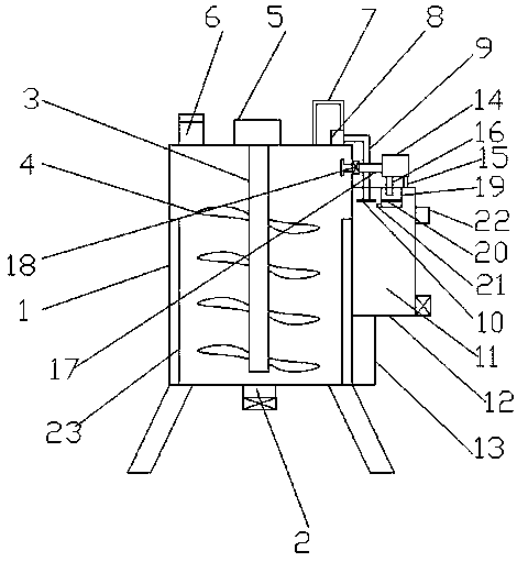
[0018] According to an embodiment of the present invention, a chemical stirred tank with waste gas treatment function is provided.

[0019] like figure 1 As shown, a chemical stirring tank with waste gas treatment function according to an embodiment of the present invention includes a stirring tank body 1, a discharge port 2 is arranged under the stirring tank body 1, and a stirring tank body 1 is provided with a stirring tank body 1. Shaft 3, a stirring blade 4 i...


PUM


Abstract

The invention discloses a chemical stirring kettle with a waste gas treatment function. The chemical stirring kettle comprises a stirring kettle body, wherein a water tank is arranged on one side of the stirring kettle body; when harmful and toxic gas is produced in the stirring kettle body, a first valve is opened, and a fan sucks air, so as to enable waste gas in the stirring kettle body to enter a second waste gas treatment box through a first gas inlet pipe and a second gas inlet pipe; an active carbon filter net is arranged in the second waste gas treatment box and is used for performingpreliminary filtering on the harmful and toxic gas, and then the gas is discharged through a waste gas outlet and enters a first waste gas treatment box; a water pump sucks water from the water tank,and the water enters the first waste gas treatment box from a water pipe; under the action of an atomization sprayer head, water flow is atomized to perform secondary filtering, so that the toxic andharmful gas meets a discharge standard and is discharged through a gas outlet. The chemical stirring kettle with the waste gas treatment function has the beneficial effects that the device is simple in structure and convenient to use; the waste gas produced in the stirring kettle body can be effectively filtered and purified to protect the health of a worker and relieve the atmospheric pollution.

Description

technical field [0001] The invention relates to the field of electromechanical chemical equipment, in particular to a chemical stirring tank with waste gas treatment function. Background technique [0002] In chemical production, the raw materials often need to be stirred and mixed. The stirring tank is often used in the mixing process and is also one of the core equipment. When some chemical raw materials are mixed and stirred, a large amount of gas and heat are often generated, especially some Environmentally hazardous substances need to be purified before they can be discharged, and gas purification devices generally have certain concentration requirements for the gases to be purified. If the concentration is too high, the purification effect will not reach the expected effect, and a large amount of heat is emitted. It may increase the temperature of the stirred tank, and the danger of explosion is more likely to occur, and the existing chemical stirring device cannot m...

Claims


Application Information

Patent Timeline
Patent Type & Authority Applications(China)
IPC IPC(8): B01J19/18B01D53/04B01D53/18
CPCB01D53/04B01D53/18B01D2253/102B01J19/18
Inventor 李方奇张鹏
Owner HEFEI OUYU AUTOMATION CO LTD
Learn More