Bridge guardrail telescopic device
A telescopic device and guardrail technology, applied in bridges, bridge parts, bridge construction and other directions, can solve the problems of poor shock absorption and seismic performance, and the expansion joint structure is not easy to repair and maintain, and achieve the effect of improving safety performance.
- Summary
- Abstract
- Description
- Claims
- Application Information
AI Technical Summary
Problems solved by technology
Method used
Image

Examples
specific Embodiment approach 1
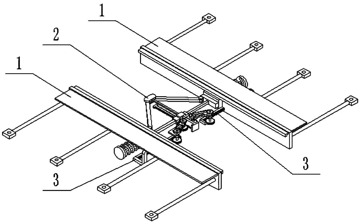
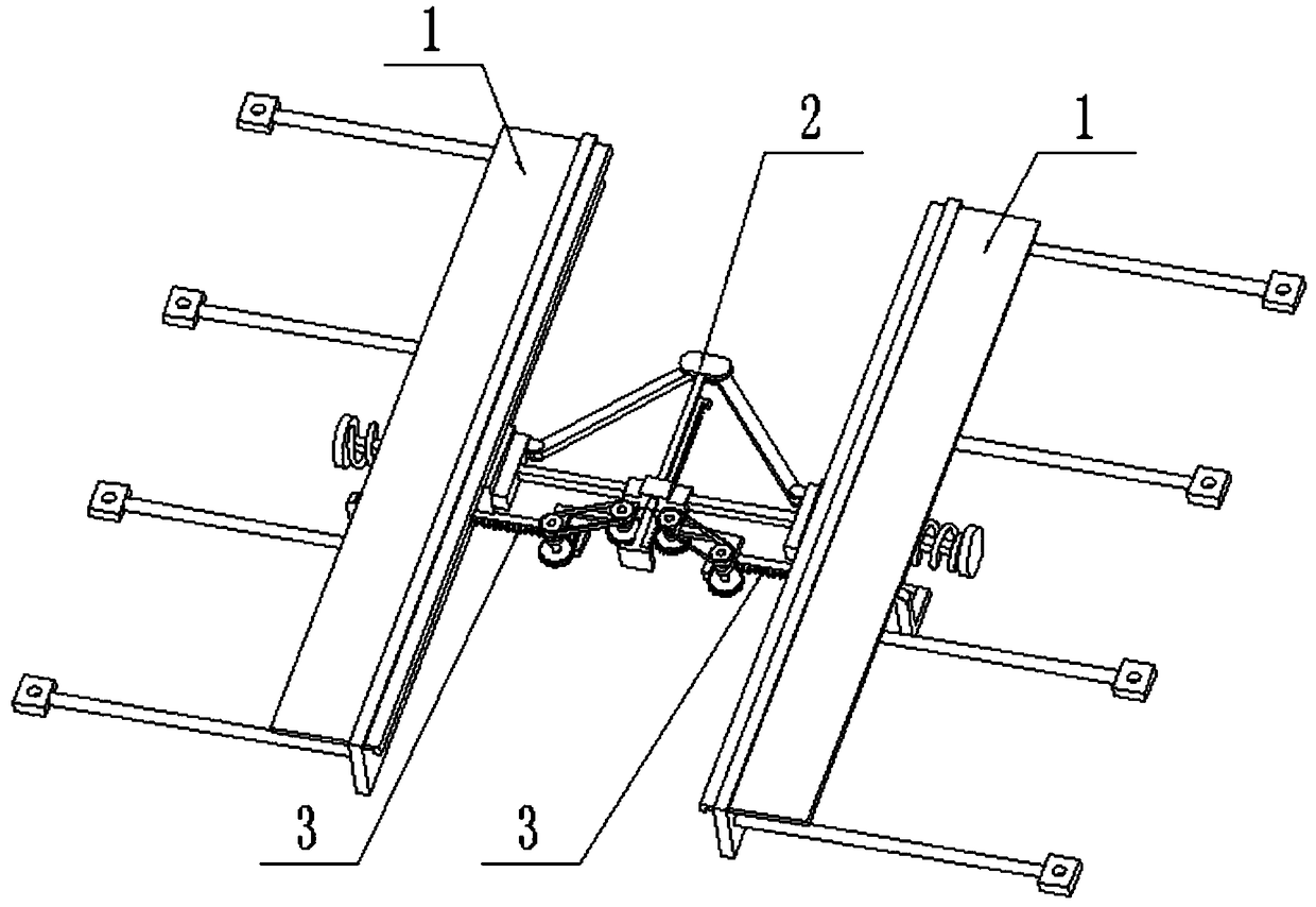
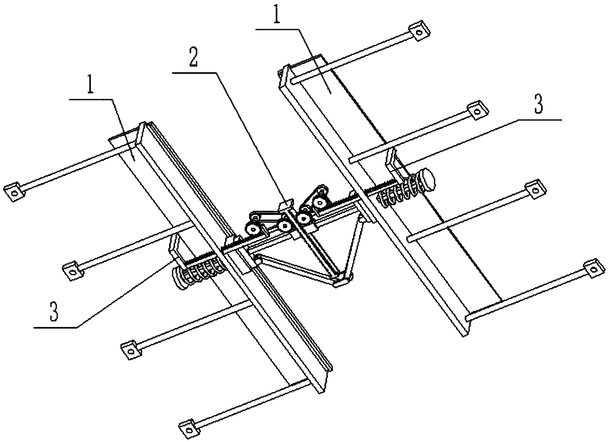
[0032] Such as Figure 1-12 As shown, a bridge guardrail telescopic device includes a guardrail panel assembly 1, a shock absorber assembly 2 and a linkage rack assembly 3, the guardrail panel assembly 1 is provided with two, and the guardrail panel assembly 1 includes a guardrail panel body 1 -1, driving anti-falling plate 1-2, multiple steel bars 1-3 and multiple positioning plates 1-4; the driving anti-falling plate 1-2 is slidably connected to the upper end of the guardrail body 1-1; guardrail The outer end of the main body 1-1 is evenly welded with a plurality of steel bars 1-3, and each of the outer ends of the plurality of steel bars 1-3 is welded with a positioning plate 1-4; the two ends of the shock absorber assembly 2 are respectively connected to two guardrails On the two guardrail body 1-1 inside the plate assembly 1; the linkage rack assembly 3 is provided with two, and the shock absorber assembly 2 is transmission-connected to the inner ends of the two linkage r...
specific Embodiment approach 2
[0033] Such as Figure 1-12As shown, the linked rack assembly 3 includes a linked rack body 3-1, a limit baffle 3-2 and an L-shaped push-pull link 3-3; the linked rack body 3-1 is meshed with a shock absorber Component 2; the inner end of the linkage rack body 3-1 is fixedly connected to the limit baffle 3-2, and the limit baffle 3-2 is blocked on the inner side of the shock absorber assembly 2, and the linkage rack body 3-1 The outer end of the L-shaped push-pull connecting rod 3-3 is fixedly connected, and the L-shaped push-pull connecting rod 3-3 is fixedly connected to the outer end of the driving anti-fall plate 1-2; The lower end of the board body 1-1. When the linkage rack assembly 3 is in use, when the shock absorber assembly 2 is working, the linkage rack body 3-1 moves inwardly under the transmission action of the shock absorber assembly 2, and the linkage rack body 3-1 passes through the L The push-pull connecting rod 3-3 pulls the driving anti-fall plate 1-2 insi...
specific Embodiment approach 3
[0034] Such as Figure 1-12 As shown, the shock absorber assembly 2 includes a hinged seat 2-1, a hinged arm 2-2, a shock absorber arm assembly 2-3, a chute seat 2-4, a guide slide bar 2-5, a bidirectional rack 2- 6. Front baffle 2-7, rear baffle 2-8, transmission wheel assembly 2-9 and linkage wheel assembly 2-10; said articulated arm 2-2 is provided with two, two articulated arms 2-2 One end is rotatably connected to the two ends of the articulated seat 2-1 through a articulated shaft, and the other ends of the two articulated arms 2-2 are rotatably connected to the two shock absorbing arm assemblies 2-3 through a articulated shaft, and the two shock absorbing arms The inner side of the component 2-3 is respectively fixedly connected to the left and right ends of the chute seat 2-4; the outer end of the shock absorbing arm component 2-3 is connected to the guardrail body 1-1; the hinged seat 2-1 Fixedly connect the front end of the guide slide bar 2-5, the guide slide bar 2...
PUM
 Abstract
Description
Claims
Application Information
 - R&D
- Intellectual Property
- Life Sciences
- Materials
- Tech Scout
- Unparalleled Data Quality
- Higher Quality Content
- 60% Fewer Hallucinations
Browse by: Latest US Patents, China's latest patents, Technical Efficacy Thesaurus, Application Domain, Technology Topic, Popular Technical Reports.
© 2025 PatSnap. All rights reserved.Legal|Privacy policy|Modern Slavery Act Transparency Statement|Sitemap|About US| Contact US: help@patsnap.com