Stop locking mechanism for worm transmission

A technology of worm drive and stop lock, applied in the direction of transmission box, transmission device, transmission device parts, etc., can solve the problems of low operation efficiency, inconvenient stop lock connection, etc., and achieve the effect of low operation efficiency

Inactive Publication Date: 2018-11-20
范科晨
View PDF4 Cites 0 Cited by
  • Summary
  • Abstract
  • Description
  • Claims
  • Application Information

AI Technical Summary

Problems solved by technology

The existing worm drive is not convenient for stop and lock, and the efficiency of the stop and lock operation for the worm drive is low

Method used


Image

  • Stop locking mechanism for worm transmission
  • Stop locking mechanism for worm transmission
  • Stop locking mechanism for worm transmission

Examples


Embodiment Construction

[0016] The preferred embodiments of the present invention will be described in detail below in conjunction with the accompanying drawings, so that the advantages and features of the present invention can be more easily understood by those skilled in the art, so as to define the protection scope of the present invention more clearly.

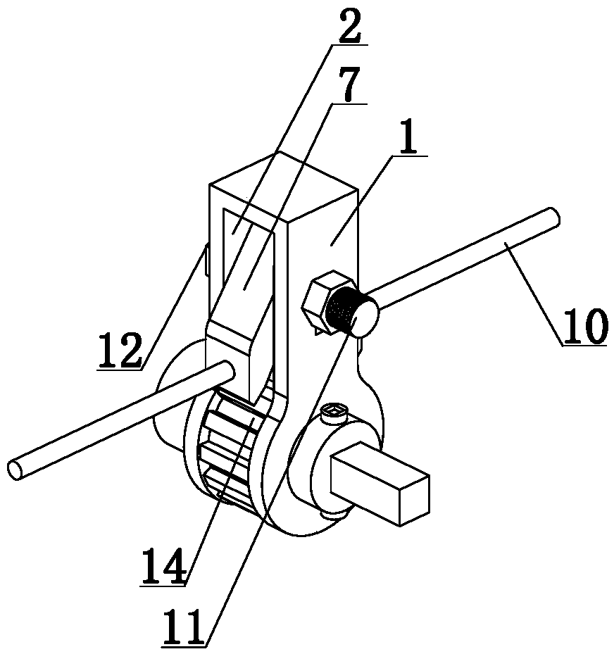
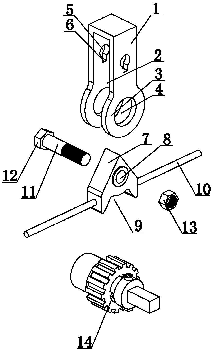
[0017] Such as Figure 1 to Figure 4 As shown, a stop locking mechanism for worm transmission includes a positioning shell 1, a positioning groove 2 is provided in the middle of the positioning shell 1, and a lock part 3 is provided on both sides of the positioning shell 1. The middle of the lock part 3 The position is provided with a lock groove 4, the two sides of the positioning shell 1 are provided with a lock hole 5 and an adjustment hole 6, and the lock hole 5 is connected with the adjustment hole 6; Connecting hole 8, connecting hole 8 communicates with locking hole 5, and connecting hole 8 and locking hole 5 are plugged with fixed rod 11;...


PUM


Abstract

The invention discloses a stop locking mechanism for worm transmission. The stop locking mechanism comprises a positioning shell; a positioning groove is formed in the middle of the positioning shell;locking parts are arranged on the lower portions of the two sides of the positioning shell correspondingly; locking grooves are formed in the middles of the locking parts; locking holes and adjustingholes are formed in the two sides of the positioning shell and communicate; a fixing block is mounted in the positioning groove; an inserting hole is formed in the middle of the fixing block and communicates with the locking holes; a fixing rod is inserted into the inserting hole and the locking holes; a locking mechanism is arranged on the lower portion of the fixing block and comprises a positioning cylinder; a plurality of positioning grooves are formed in the outer circumferential face of the positioning cylinder; a limiting cylinder is arranged at one end of the positioning cylinder, anda square strip is arranged at the other end of the positioning cylinder; the outer circumferential face of the positioning cylinder is sleeved with a locking wheel, and a plurality of inserting blocks are arranged on the inner circumferential face of the locking wheel and mounted in the positioning grooves; and a plurality of locking grooves are formed in the outer circumferential face of the locking wheel. Through the locking grooves, the locking wheel can be engaged with the outer circumferential face of a worm, and can conduct stop locking on the outer circumferential face of the worm.

Description

technical field [0001] The invention relates to a locking mechanism, in particular to a stop locking mechanism for worm drive. Background technique [0002] The worm drive refers to the deceleration transmission with the worm as the main action. When the reverse stroke is not self-locking, the worm gear can also be used as the main action to speed up the transmission. The worm drive is composed of a worm and a worm gear, and the worm is generally the active part. Worms, like threads, can be divided into right-handed and left-handed, which are called right-handed and left-handed worms, respectively. The existing worm drive is inconvenient for stop locking, and the operation efficiency of stop lock for the worm drive is low. Contents of the invention [0003] The present invention mainly solves the technical problems existing in the prior art, thereby providing a positioning cylinder to position and install the lock wheel through the positioning groove, the lock wheel can ...

Claims


Application Information

Patent Timeline
Patent Type & Authority Applications(China)
IPC IPC(8): F16H1/16F16H57/02F16H57/023
CPCF16H1/16F16H57/02F16H57/023
Inventor 不公告发明人
Owner 范科晨
Why Eureka
Try Eureka