
Time domain waveform-controllable laser generation system and method

A time-domain waveform and laser technology, applied in the laser field, can solve problems such as uncontrollable pulse shape, restricted application, and difficulty in achieving high power

Active Publication Date: 2018-11-20
TSINGHUA UNIV
View PDF4 Cites 4 Cited by
  • Summary
  • Abstract
  • Description
  • Claims
  • Application Information

AI Technical Summary

Problems solved by technology

And in the structure of Master Oscillator Power-Amplifier (MOPA) to obtain high power, the gain of the amplifier stage will change dynamically during continuous operation, and the generated pulse shape is uncontrollable. In the prior art, the laser power It is difficult to control the high power requirements, or although the power requirements can be met, the cost is too high, and the laser with uncontrolled power may cause optical damage and seriously restrict the application.

Method used


Image

  • Time domain waveform-controllable laser generation system and method
  • Time domain waveform-controllable laser generation system and method
  • Time domain waveform-controllable laser generation system and method

Examples


no. 4 example

[0046] On the basis of the laser generation system with controllable time-domain waveform provided by the foregoing embodiments of the present invention, a laser generation method with controllable time-domain waveform will naturally be obtained. In order to enable readers to better understand the method, the fourth embodiment of the present invention provides a flow chart of steps for specifically implementing the method on the basis of the foregoing embodiments. For details, please refer to Figure 4 , Figure 4 It is a step-by-step flow chart of the laser generation method with controllable time-domain waveform in the fourth embodiment of the present invention. The method can be realized by the laser generation system with controllable time-domain waveform in any of the foregoing embodiments. The laser generation system with controllable time-domain waveform in the implementation of the method of this embodiment has similar steps and principles, so in this embodiment, the ...


PUM


Abstract

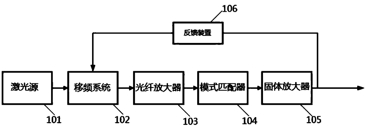
The embodiment of the invention provides a time domain waveform-controllable laser generation system. The time domain waveform-controllable laser generation system comprises a frequency shift system,an optical fiber amplifier, a mode matcher, a solid amplifier and a feedback device, wherein the frequency shift system is connected with the optical fiber amplifier and is used for receiving laser and modulating a frequency of the laser in a real time, the optical fiber amplifier is connected with the mode matcher and is used for amplifying a power of the laser, the mode matcher is connected withthe solid amplifier and is used for performing mode matching on the laser after power amplification and pumping light in the solid amplifier, the solid amplifier is connected with the feedback deviceand is used for performing power amplification on the laser of the mode matcher after mode matching and outputting time domain waveform-controllable laser, and the feedback device is connected with the frequency shift system and is used for converting a light signal to an electrical signal and sending the electrical signal to the frequency shift system. The embodiment of the invention also provides a time domain waveform-controllable laser generation method which is implemented by the system. By the time domain waveform-controllable laser generation system, the laser frequency can be effectively modulated, and laser pulse shape conforming to requirement is acquired.

Description

technical field [0001] Embodiments of the present invention relate to the field of laser technology, and in particular to a laser generation system and method with controllable time-domain waveform. Background technique [0002] Time-domain properties are an important property of laser pulses. The pulsed laser method to obtain high peak power generally adopts Q-switching technology. The inherent characteristic of Q-switched laser is that as the repetition rate increases, the pulse width will also increase. And in the structure of Master Oscillator Power-Amplifier (MOPA) to obtain high power, the gain of the amplifier stage will change dynamically during continuous operation, and the generated pulse shape is uncontrollable. In the prior art, the laser power It is difficult to achieve the high power requirement by the control of the laser, or the power requirement can be met, but the cost is too high, and the laser with uncontrolled power may cause optical damage and serious...

Claims


Application Information

Patent Timeline
IPC IPC(8): H01S3/00H01S3/067H01S3/10
CPCH01S3/0092H01S3/06754H01S3/10007
Inventor 柳强聂明明江业文
Owner TSINGHUA UNIV
Learn More