Supercharge Your Innovation With Domain-Expert AI Agents!

Drive circuit and method for driving synchronous rectifier and switching power supply for synchronous rectifier

一种同步整流器、驱动电路的技术,应用在电子开关、高效电力电子转换、仪器等方向,能够解决效果不明显等问题,达到容易调节、防止误关断、实现调节的效果

Active Publication Date: 2018-11-20
CHENGDU MONOLITHIC POWER SYST
View PDF3 Cites 6 Cited by
  • Summary
  • Abstract
  • Description
  • Claims
  • Application Information

AI Technical Summary

Problems solved by technology

[0006] However, although the above method can reduce false triggering operations, the effect is still not obvious, and a method that can effectively prevent false triggering is needed

Method used


Image

  • Drive circuit and method for driving synchronous rectifier and switching power supply for synchronous rectifier
  • Drive circuit and method for driving synchronous rectifier and switching power supply for synchronous rectifier
  • Drive circuit and method for driving synchronous rectifier and switching power supply for synchronous rectifier

Examples


Embodiment Construction

[0017] Specific embodiments of the present invention will be described in detail below, and it should be noted that the embodiments described here are only for illustration, not for limiting the present invention. In the following description, numerous specific details are set forth in order to provide a thorough understanding of the present invention. It will be apparent, however, to one of ordinary skill in the art that these specific details need not be employed to practice the present invention. In other instances, well-known circuits, materials or methods have not been described in detail in order to avoid obscuring the present invention.

[0018] Throughout this specification, reference to "one embodiment," "an embodiment," "an example," or "example" means that a particular feature, structure, or characteristic described in connection with the embodiment or example is included in the present invention. In at least one embodiment. Thus, appearances of the phrases "in on...


PUM


Abstract

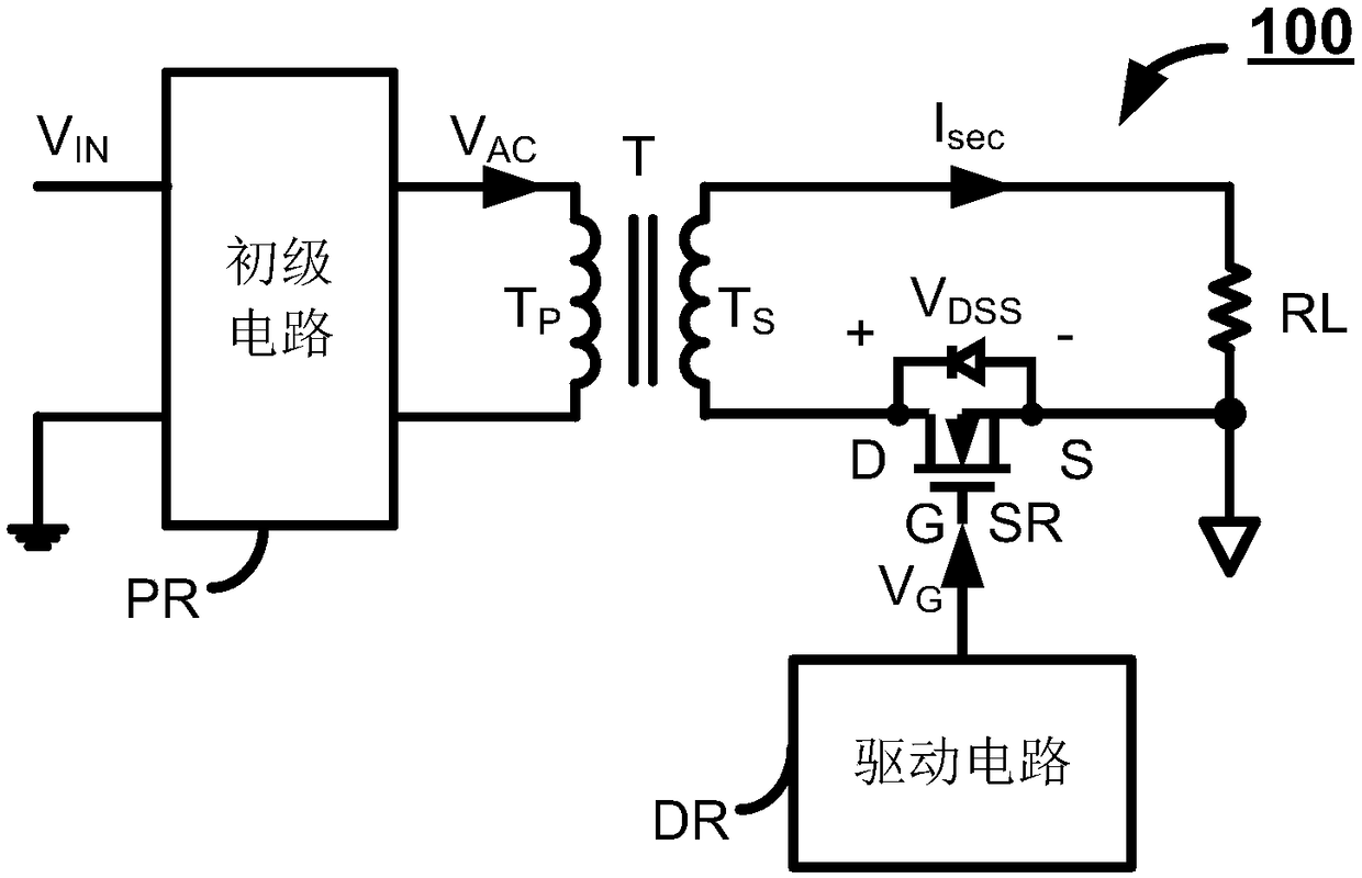
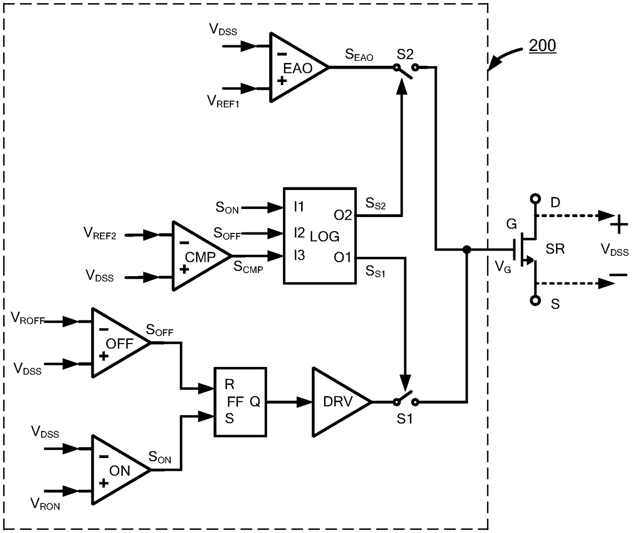
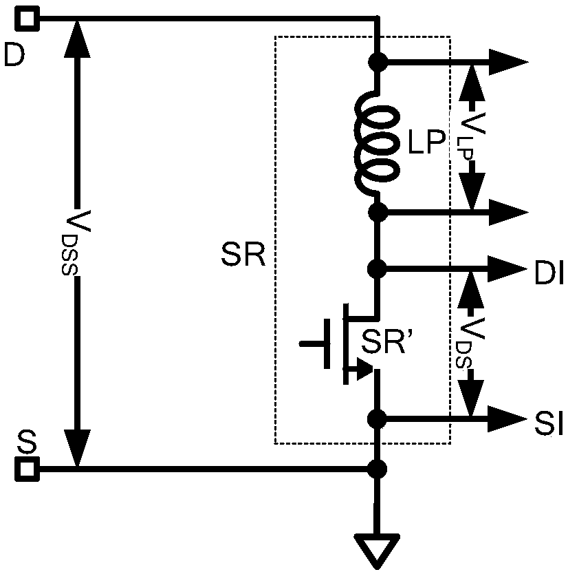
The invention discloses a drive circuit and method for driving a synchronous rectifier. The synchronous rectifier comprises a drain terminal, a source terminal and a gate terminal, wherein drain-source detection voltage is formed between the drain terminal and the source terminal of the synchronous rectifier; and gate voltage is formed on the gate terminal. When the drain-source detection voltagereaches set reference voltage, the gate voltage is reduced to keep the drain-source detection voltage at lower reference voltage. By using the drive circuit and method, the actual shutdown time of thesynchronous rectifier is closer to the ideal shutdown time, so that the synchronous rectifier can be more effectively prevented from being shut down by mistake; and furthermore, the drain-source detection voltage can be adjusted when being relatively high, and adjustment of the synchronous rectifier is easier to implement by using the same adjusting circuit.

Description

technical field [0001] This invention relates to electronic circuits and, more particularly, to synchronous rectification. Background technique [0002] In the synchronous rectification resonant converter, it is necessary to sample the drain-source voltage of the synchronous rectification MOS tube, and adjust the drain-source voltage through the regulating circuit to maintain it at a preset threshold, so as to ensure that the output voltage of the synchronous rectification resonant converter is as desired reach the target voltage. In addition, it is necessary to compare the drain-source voltage of the synchronous rectification MOS transistor with the reverse threshold voltage. When the drain-source voltage of the synchronous rectification MOS transistor reaches the reverse threshold voltage, the synchronous rectification MOS transistor needs to be turned off to prevent current reversal. Towards. [0003] The method of sampling the drain-source voltage of the MOS transistor...

Claims


Application Information

Patent Timeline
Patent Type & Authority Applications(China)
IPC IPC(8): H02M3/335
CPCH02M3/33592H02M1/08H03K17/18H03K2217/0027Y02B70/10H02M3/33576
Inventor 冯林葉家佑
Owner CHENGDU MONOLITHIC POWER SYST
Features
  • R&D
  • Intellectual Property
  • Life Sciences
  • Materials
  • Tech Scout
  • Unparalleled Data Quality
  • Higher Quality Content
  • 60% Fewer Hallucinations
Learn More