
Book End System

A book stand and vertical plate technology, applied in the field of book stand systems, can solve problems such as loosening and collapse, and achieve the effect of reducing the probability of loosening and increasing frictional resistance.

Inactive Publication Date: 2019-12-27
CHONGQING JIAOTONG UNIVERSITY
View PDF10 Cites 0 Cited by
  • Summary
  • Abstract
  • Description
  • Claims
  • Application Information

AI Technical Summary

Problems solved by technology

In the prior art, bookends are mostly made of iron, stainless steel and other materials in an L shape and appear in pairs. A single bookend generally includes a bottom plate and a baffle. The bottom plate is arranged horizontally, and the baffle is vertically arranged. structure, when in use, the book stands on the bottom plate and leans against the baffle plate, and exerts a large outward force on the baffle plate of the book end. When there are too many books, if the books resist When the books are close together and each book is kept in an upright state, the force of the books on the baffle is small, and when the books are tilted due to their own balance, the force caused by the books on the baffle will force the baffle to move outward , when the elastic deformation of the baffle itself cannot withstand the force from the books on the baffle, the baffle will drive the bottom plate to move outward together, which will cause the overall movement of the bookend as a whole. As a result of this movement, the books cannot Keep the state of being clamped by the book end, but it will loosen and even collapse

Method used


Image

  • Book End System
  • Book End System
  • Book End System

Examples


Embodiment Construction

[0021] The technical solutions in the embodiments of the present invention will be clearly and completely described below in conjunction with the drawings in the embodiments of the present invention. Obviously, the described embodiments are only part of the embodiments of the present invention, not all of them. Based on the embodiments of the present invention, all other embodiments obtained by persons of ordinary skill in the art without making creative efforts fall within the protection scope of the present invention.

[0022] It should be noted that all directional indications (such as up, down, left, right, front, back...) in the embodiments of the present invention are only used to explain the relative relationship between the various components in a certain posture (as shown in the accompanying drawings). When the positional relationship, movement conditions, etc., if the specific posture changes, the directional indication will also change accordingly.

[0023] In addit...


PUM


Abstract

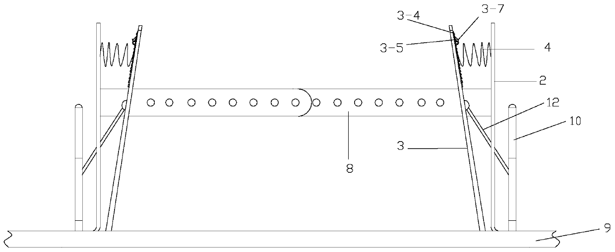
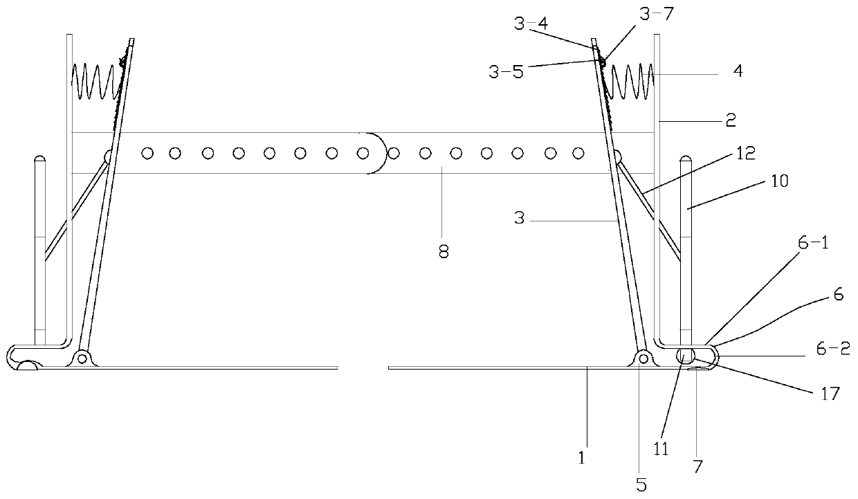
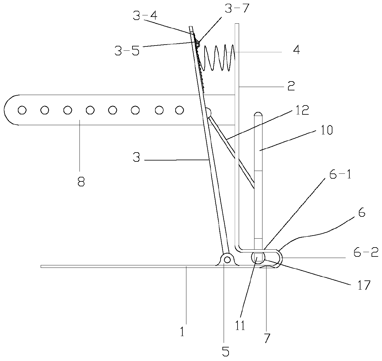
The invention discloses a book end system. The book end system comprises two book end units which are arranged in pairs and rails arranged on the two sides of the two book end units; each book end unit comprises a bottom plate part, a vertical plate part which is integrally shaped with the bottom plate part, a movable baffle plate which is arranged between the bottom plate part and the vertical plate part, and a supporting positioning mechanism which is used for cooperating with the rails, the lower end of the movable baffle plate can be rotatably connected to the bottom plate, and the upper portion of the movable baffle plate is connected with the vertical plate part through a first spring member; in the process where the movable baffle plate gets close towards the vertical plate part ofa book end body, a sliding block is driven to move downwards by a connecting rod to force two elastic supporting arms of an elastic supporting member to expand outwards, so that supporting legs whichare arranged on all elastic supporting arms are driven to move horizontally outwards, the friction resistance between the rear ends of the supporting legs and the rails is increased, the purpose of positioning the book end units on the rails relying on books is eventually achieved, and the possibility that the books fall down or loosen is greatly reduced.

Description

technical field [0001] The invention relates to the field of daily necessities, in particular to a book end system. Background technique [0002] A bookend is an object used to support books to stand stably, which can prevent a row of standing books from tilting and tilting, so as to prevent the books from being bent, bent or damaged. Bookends can also be used to sort out different types of books. Libraries often use bookends to organize bookshelves with gaps. Companies and individuals can also use bookends to open up neat space for books and materials on flat desks. In the prior art, bookends are mostly made of iron, stainless steel and other materials in an L shape and appear in pairs. A single bookend generally includes a bottom plate and a baffle. The bottom plate is arranged horizontally, and the baffle is vertically arranged. structure, when in use, the book stands on the bottom plate and leans against the baffle plate, and exerts a large outward force on the baffle p...

Claims


Application Information

Patent Timeline
Patent Type & Authority Patents(China)
IPC IPC(8): A47B65/00
CPCA47B65/20
Inventor 胡启国胡艳敏
Owner CHONGQING JIAOTONG UNIVERSITY
Learn More