Ligating wire terminal pusher for orthodontics

A propeller and orthodontic technology, applied in the field of medical equipment, can solve problems such as inconvenient use, troubles for medical staff, and inability to adjust propulsion according to needs, so as to achieve the effect of convenient use and convenience for medical staff

Active Publication Date: 2020-12-18
温庆芳
View PDF1 Cites 1 Cited by
  • Summary
  • Abstract
  • Description
  • Claims
  • Application Information

AI Technical Summary

Problems solved by technology

[0002] In the process of orthodontic treatment, the common method is to use ligature wire to ligate, and the propeller is a needle holder, but the existing needle holder basically does not have the propulsion function, requiring frequent replacement of instruments, which greatly reduces work efficiency, such as The patent application publication number 201620806469.9 discloses a ligature wire end pusher for orthodontics, including a first pincer rod, a second pincer rod, a first pincer beak, a second pincer beak, a pin shaft, a first finger ring, a Two finger rings, the first pincer bar and the second pincer bar are connected by pin shafts, the first pincer beak and the second pincer beak are respectively located at the ends of the first pincer bar and the second pincer bar, at the first pincer beak, the second pincer beak The ends of the pliers beaks are respectively provided with opening slots. However, during the use of the above patents, they cannot be adjusted and pushed according to the needs. Frequent replacement of instruments is required, which is inconvenient to use and brings great troubles to medical staff.

Method used


Image

  • Ligating wire terminal pusher for orthodontics
  • Ligating wire terminal pusher for orthodontics

Examples


Embodiment Construction

[0014] The following will clearly and completely describe the technical solutions in the embodiments of the present invention with reference to the accompanying drawings in the embodiments of the present invention. Obviously, the described embodiments are only some, not all, embodiments of the present invention. Based on the embodiments of the present invention, all other embodiments obtained by persons of ordinary skill in the art without making creative efforts belong to the protection scope of the present invention.

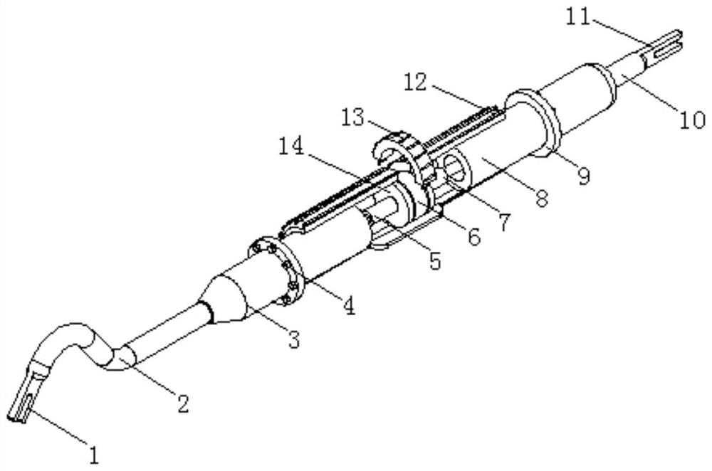
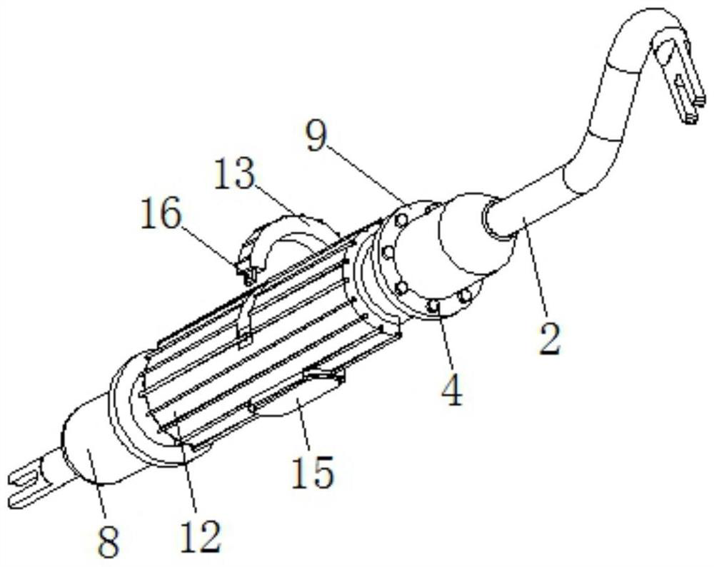
[0015] see Figure 1-2 , the present invention provides a technical solution: a ligature wire end pusher for orthodontics, including a handle 12, a through groove is provided in the middle of the handle 12, and two sets of baffles 14 symmetrically distributed are arranged in the middle of the through groove A power supply 6 is arranged between the baffles 14, wherein one set of baffles 14 is connected to one end of the first electric telescopic rod 5 on one si...


PUM


Abstract

The invention discloses a ligation wire end propeller for orthodontic treatment, the ligation wire end propeller comprises a handle, the middle of the inner part of the handle is provided with a through groove, the middle position of the through groove is provided with two sets of symmetrically distributed baffles, a power supply is disposed between the baffles, one side of one set of baffles awayfrom the power supply is connected to one end of a first electric telescopic rod, the other end of the first electric telescopic rod is connected with a left sliding rod, one side of the other set ofbaffles away from the power supply is connected to one end of a second electric telescopic rod, the other end of the second electric telescopic rod is connected with a right sliding rod, the handle is provided with an arc-shaped through groove on a side close to the power supply, adjustable propelling can be performed according to requirements by the sliding of the left and right sliding rods inthe handle, and the power supply is detachable and changable and the illumination function of an LED illumination lamp so that frequent change of the instruments is not needed. The ligation wire end propeller for orthodontic treatment is convenient to use, and brings great convenience to medical staff.

Description

technical field [0001] The invention relates to the technical field of medical devices, in particular to a ligature wire end pusher for orthodontics. Background technique [0002] In the process of orthodontic treatment, the common method is to use ligature wire to ligate, and the propeller is a needle holder, but the existing needle holder basically does not have the propulsion function, requiring frequent replacement of instruments, which greatly reduces work efficiency, such as The patent application publication number 201620806469.9 discloses a ligature wire end pusher for orthodontics, including a first pincer rod, a second pincer rod, a first pincer beak, a second pincer beak, a pin shaft, a first finger ring, a Two finger rings, the first pincer bar and the second pincer bar are connected by pin shafts, the first pincer beak and the second pincer beak are respectively located at the ends of the first pincer bar and the second pincer bar, at the first pincer beak, the ...

Claims


Application Information

Patent Timeline
Patent Type & Authority Patents(China)
IPC IPC(8): A61C7/28
CPCA61C7/28
Inventor 温庆芳张艳玲雷东辉
Owner 温庆芳
Why Eureka
Try Eureka