Tool holder

A tool holder and frame technology, applied in the field of C-shaped tool holders, can solve problems such as excessive bending angles

Inactive Publication Date: 2018-11-23
BOLLHOFF VERBINDUNGSTECHNIK GMBH
View PDF11 Cites 0 Cited by
  • Summary
  • Abstract
  • Description
  • Claims
  • Application Information

AI Technical Summary

Problems solved by technology

[0005] However, in many connection methods, excessive bending angles are undesir

Method used


Image

  • Tool holder
  • Tool holder
  • Tool holder

Examples


Example Embodiment

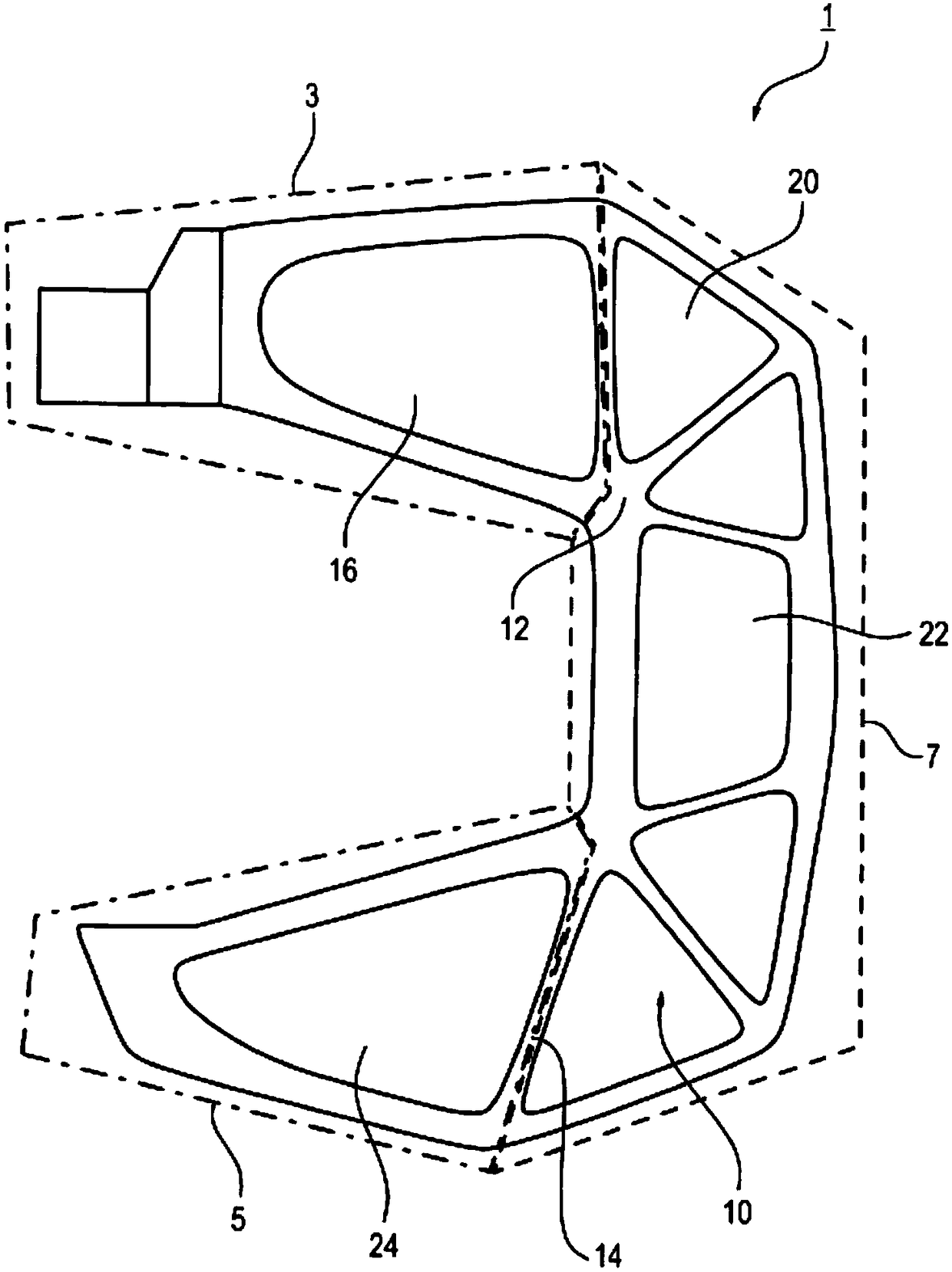
[0049] According to a preferred embodiment, the present invention discloses in a schematic side view such as figure 1 C-shaped tool holder 1 shown. They are generally known for their use in rivet fixing devices or riveting tools, for example. They are included in figure 1 It extends horizontally and passes through the connecting leg 7 ( figure 1 Dotted line in) a first leg 3 and a second leg 5 connected to each other (see figure 1 Dotted line in).

[0050] The first leg 3 and the second leg 5 and the connecting leg 7 are composed of an integral frame structure 10. In the frame structure 10, they are integral with each other and there are no leg modules that are connected or connectable. In this case, the whole means that the frame structure 10 forms a continuous whole and cannot be divided into its various parts without destroying it. Correspondingly, the leg portions 3, 5, 7 are not connected to each other by force fit, friction or surface bonding connection elements.

[0051] ...


PUM


Abstract

A C-shaped tool holder consisting of an integral frame structure that is delimited by an inner and an outer edge, each C-shaped, in which the C-shaped edges are made from and are connected to each other by at least five multiple-vertex frame bodies that are integrated into the frame structure, in particular triangles, quadrilaterals and pentagons, wherein in each case an inner side of the individual multiple-vertex frame bodies is a connecting surface, continuously curving along a circumferential direction, along the sides of the respective multiple-vertex frame body, and the inner and the outer C-shaped edge is each delimited to the outside by a continuously curving lateral surface.

Description

1. Field of invention [0001] The present invention relates to a C-shaped tool holder comprising a one-piece frame structure, especially a C-shaped frame, and a connecting device made using the above-mentioned C-shaped frame, especially a rivet fixing device. 2. Background of the invention [0002] In known joining or forming applications, the forces generated during pressing, riveting or punching must be dampened by proper frame design. A C-frame design known for this purpose is commonly used. Especially in such automated processes where C-frame tools are driven by automatic machinery, the weight of the C-frame plays an important role. [0003] A C-frame known in the prior art is described in DE69911040T2. This light design C-frame is a design consisting of rod elements firmly connected at connection points (trusses). These rod elements are designed as triangular structures. To optimize the material stresses under connection point loads, the rod elements are rounded into...

Claims


Application Information

Patent Timeline
IPC IPC(8): B23B21/00B21J15/10
CPCB21J15/10B23Q1/0054B23K11/318B21J15/30B23K26/38B23K26/40B23K26/402B23K2101/20B23K2101/24B23K2103/04B23K2103/10B23K2103/16B21J15/32
Inventor 斯特凡·勒林
Owner BOLLHOFF VERBINDUNGSTECHNIK GMBH
Why Eureka
Try Eureka