Method and device for controlling a turning operation

Inactive Publication Date: 2005-08-09
STAFFANSBODA CIE
View PDF5 Cites 64 Cited by
  • Summary
  • Abstract
  • Description
  • Claims
  • Application Information

AI Technical Summary

Benefits of technology

[0005]An object of the present invention is to provide a method

Problems solved by technology

When a workpiece is worked by means of a lathe, a certain degree of unevenness always arises in the turned surface.
A low feedin

Method used


Image

  • Method and device for controlling a turning operation
  • Method and device for controlling a turning operation
  • Method and device for controlling a turning operation

Examples


Embodiment Construction

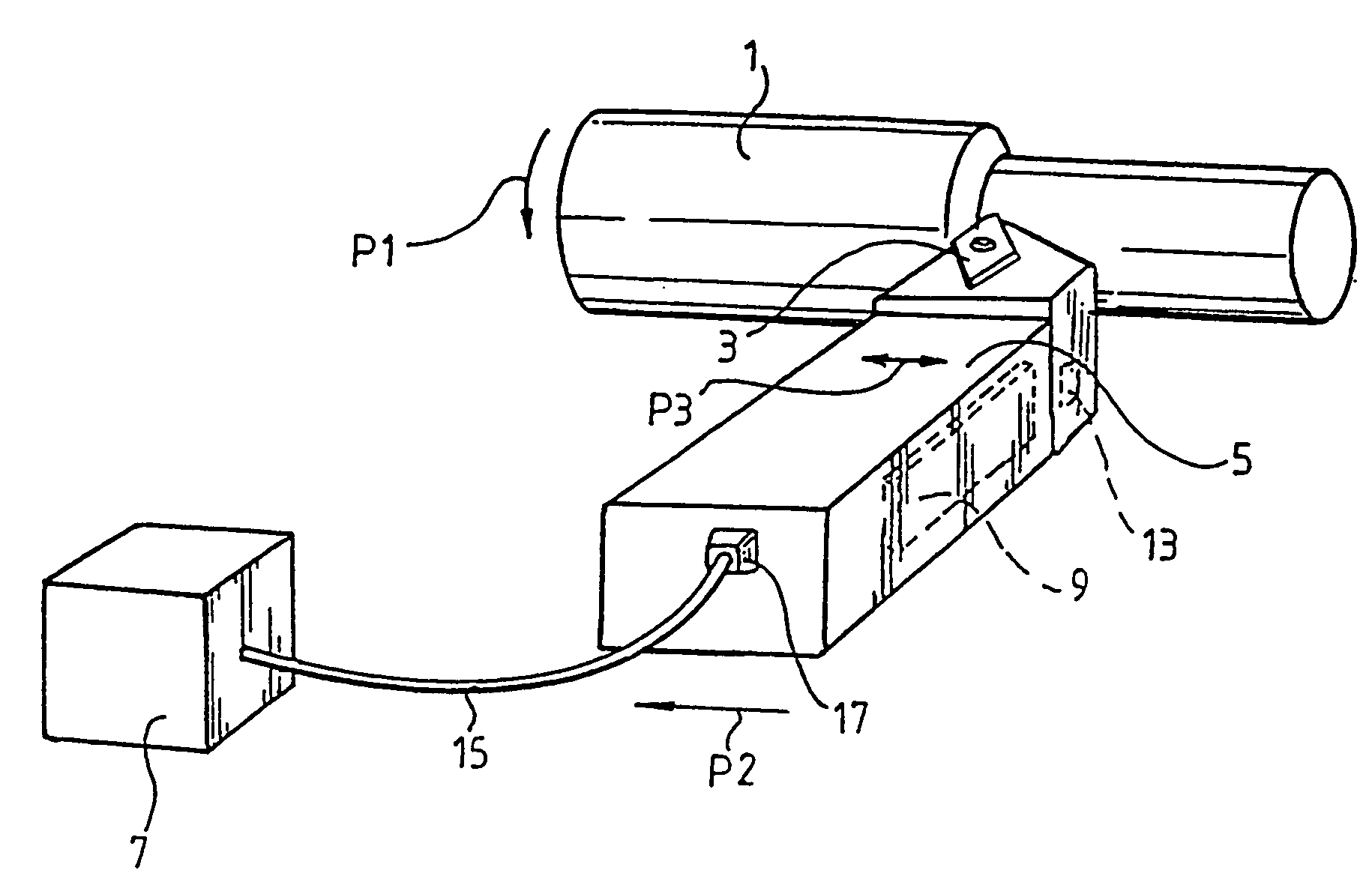
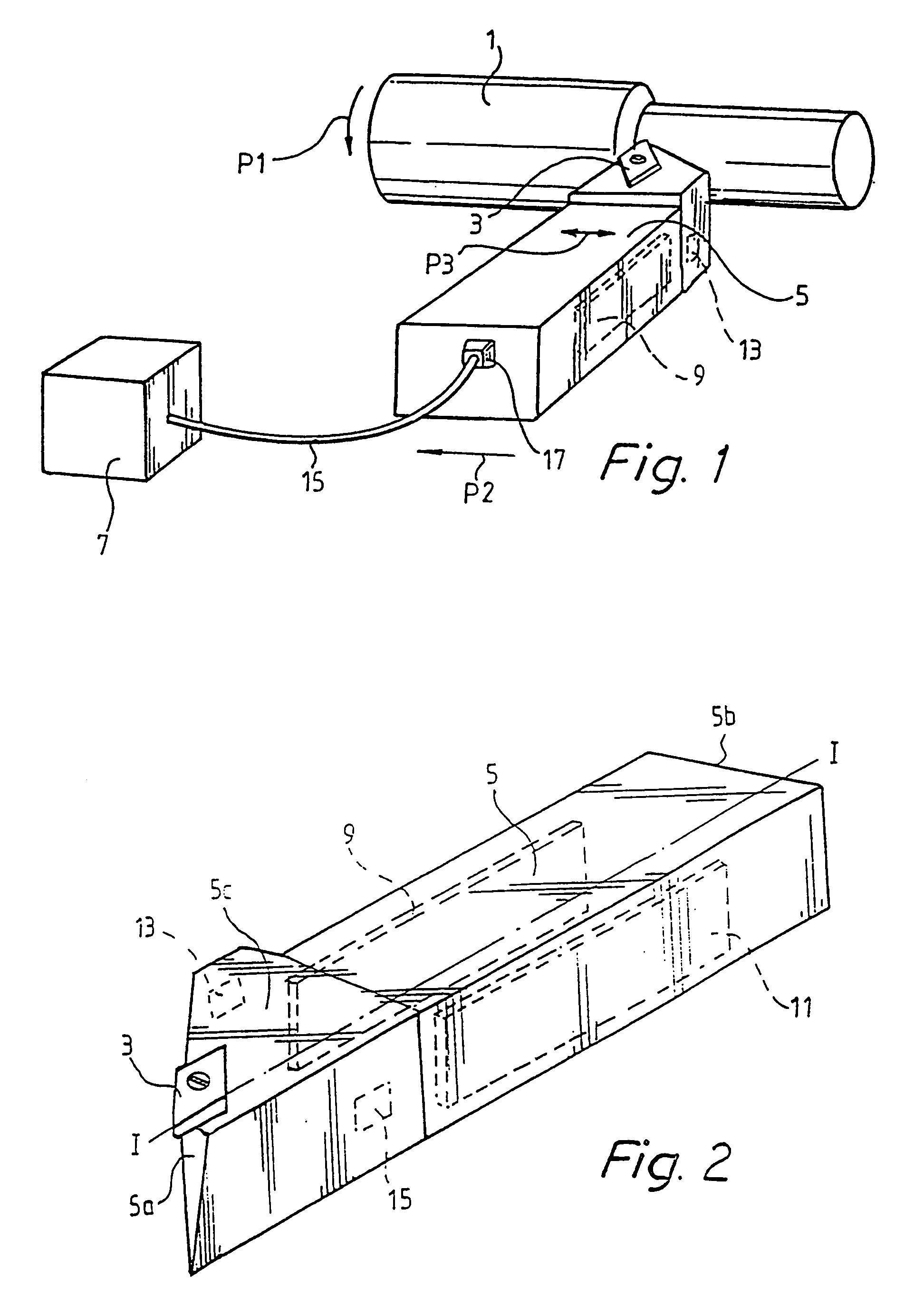
[0011]FIG. 1 illustrates essentially an embodiment of the device and also of the tool holder according to the invention. Reference numeral 1 indicates a workpiece which is arranged in a lathe and rotates in the direction indicated by arrow P1. The workpiece 1 is worked by means of a tool 3, here referred to as insert, which is rigidly connected to a tool holder 5, here referred to as insert holder. The device comprises a control system with a control unit 7 and two actuators 9, 11, one of which is indicated by dashed lines in FIG. 1 and both of which are shown in FIG. 2, which illustrates the actual tool holder 5 in a different view.

[0012]Each actuator 9, 11 comprises an active element 9, 11, which here is a piezoceramic element. A piezoceramic element can in turn be designed as a unit or advantageously be made up as a so-called stack and / or of several partial elements. Thus the element can be a solid body or a plurality of individual, but composed and interacting bodies. The active...


PUM

PropertyMeasurementUnit
Speedaaaaaaaaaa
Surface smoothnessaaaaaaaaaa

Abstract

A device increases the surface smoothness of a turned surface. The device comprising a control system with a control unit and an actuator connectible to the control unit and connectible with a tool holder. The actuator in adapted to impart a vibrating motion in the lateral direction to the tool holder. A method will also increase the surface smoothness of a turned surface, comprising the step of controlling the vibrations of the tool holder during turning. The method also comprises the step of imparting a vibrating motion in the lateral direction to the tool holder. Moreover, a turning lathe and a turning tool holder which like the device are designed to generate vibrating motion in the lateral direction.

Description

[0001]This application is the national phase under 35 U.S.C. § 371 of PCT International Application No. PCT / SE99 / 01884 which has an International filing date of Oct. 19, 1999, which designated the United States of America and was published in English.FIELD OF THE INVENTION[0002]The present invention relates to a method and a device for controlling a turning operation, more specifically a method, a device, a turning tool holder and a turning lathe for increasing the surface smoothness of a turned surface.BACKGROUND ART[0003]When a workpiece is worked by means of a lathe, a certain degree of unevenness always arises in the turned surface. The unevenness can be resembled to stripes or threads and arises owing to the cutting edge of the working tool having a limited nose radius. The tools are manufactured with a plurality of different standard radii. The radius of the cutting edge results, in combination with the feeding, in a surface which is not quite smooth. A low feeding speed certa...

Claims


Application Information

Patent Timeline
IPC IPC(8): B23B29/00B23B25/00B23B25/02B23B29/12G05B19/18B23B1/00
CPCB23B25/02B23B29/125G05B19/18G05B2219/37432Y10T82/2533G05B2219/40069G05B2219/41344G05B2219/45136Y10S82/904G05B2219/39241
Inventor CLAESSON, INGVARLAGO, THOMASHAKANSSON, LARS
Owner STAFFANSBODA CIE
Why Eureka
Try Eureka