
Mobile phone shell polishing device

A technology of polishing device and mobile phone case, which is applied to grinding/polishing equipment, grinding workpiece support, grinding machine, etc., can solve the problems of high cost, low polishing efficiency, limiting production efficiency of mobile phone case, etc., and achieve the effect of improving processing efficiency.

Inactive Publication Date: 2018-11-23
郑空军
View PDF6 Cites 2 Cited by
  • Summary
  • Abstract
  • Description
  • Claims
  • Application Information

AI Technical Summary

Problems solved by technology

The metal mobile phone case includes a polishing process in the actual processing process to achieve the purpose of polishing, eliminate metal burrs on the mobile phone case and improve the flatness of the mobile phone case. In the prior art, polishing robots are generally used to implement the above polishing process. The polishing robot includes a polishing robot arm. Although the polishing robot has a high degree of polishing automation, the polishing efficiency is low. It is necessary to purchase a large number of polishing robots to meet large-scale industrial production, which also causes a significant increase in cost; the existing Generally, the polishing machine can only clamp one mobile phone case blank. When a mobile phone case blank is polished, it must be stopped, and the polished mobile phone case blank on the fixture can be removed before the next mobile phone case can be processed. Polishing processing, which severely limits the production efficiency of mobile phone cases

Method used


Image

  • Mobile phone shell polishing device
  • Mobile phone shell polishing device
  • Mobile phone shell polishing device

Examples


Embodiment Construction

[0014] to combine Figure 1 to Figure 7 , the present invention is further described:

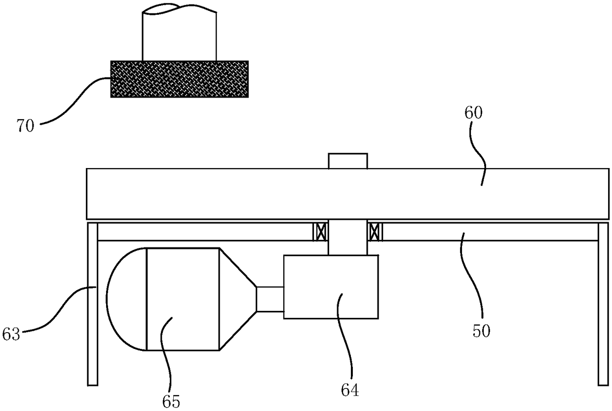
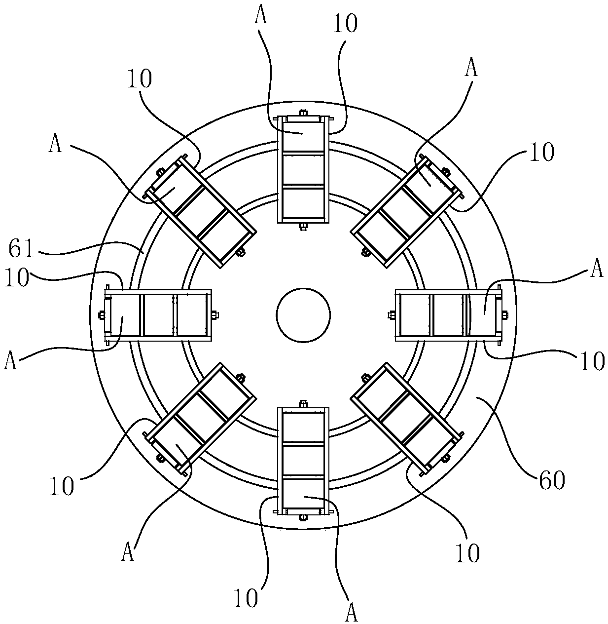
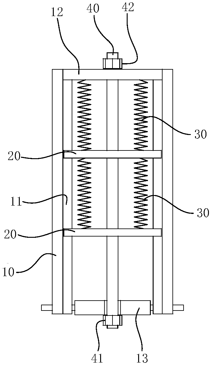
[0015] The mobile phone shell polishing device includes a workbench 50, on which a chuck 60 is rotatably arranged, the disk surface of the chuck 60 is horizontal, and the drive mechanism drives the chuck 60 to rotate around the axis, and the chuck 60 The upper disk surface is provided with an annular clamping groove 61, the annular clamping groove 61 is concentric with the chuck 60, and the clamp is arranged on the circular clamping groove 61, and a plurality of clamps are arranged at intervals along the annular clamping groove 61. The top of the disk 60 is rotated with a polishing disk 70. The fixture includes a rectangular box body 10, and a clamping plate 20 is slidably arranged in the box opening of the rectangular box body 10. The plate surface of the clamping plate 20 is vertical and along the The longitudinal direction of the rectangular box body 10 is provided with a plurality of i...


PUM


Abstract

The invention relates to a mobile phone shell polishing device which comprises a workbench. A clamping disc is rotationally arranged on the workbench, the disc face of the clamping disc is horizontal,a driving mechanism drives the clamping disc to rotate around the axis, an annular clamping groove is formed in the upper disc face of the clamping disc, multiple clamps are arranged on the annular clamping groove, the clamps are arranged at intervals along the annular clamping groove, a polishing disc is rotationally arranged above the clamping disc, and each clamp comprises a rectangular box, wherein a clamping plate is slidably arranged inside a box opening of the rectangular box, the sliding direction of the clamping plate is parallel to the length direction of the rectangular box, the clamping plates are connected through a spring, the clamping plates and one ends of the rectangular boxes are connected through a spring, the length direction of the springs are parallel to the length direction of the rectangular boxes, after a mobile phone shell on the clamps is machined, the driving mechanism is started, the clamp at the next position is converted to the portion below the polishing disc, the polished mobile phone shell is disassembled, the mobile phone shell to be polished is installed, the steps are executed repeatedly and circularly, the mobile phone shell can be continuously machined, and the machining efficiency of the mobile phone shell can be remarkably improved.

Description

technical field [0001] The invention relates to the technical field of mobile phone parts production, in particular to a mobile phone shell polishing device. Background technique [0002] At present, more and more mobile phone casings are made of metal materials. The grip feeling of metal mobile phone casings is obviously better than that of ordinary plastics, so it can also effectively improve the comfort of mobile phones. The metal mobile phone case includes a polishing process in the actual processing process to achieve the purpose of polishing, eliminate metal burrs on the mobile phone case and improve the flatness of the mobile phone case. In the prior art, polishing robots are generally used to implement the above polishing process. The polishing robot includes a polishing robot arm. Although the polishing robot has a high degree of polishing automation, the polishing efficiency is low. It is necessary to purchase a large number of polishing robots to meet large-scale ...

Claims


Application Information

Patent Timeline
Patent Type & Authority Applications(China)
IPC IPC(8): B24B19/00B24B41/06
CPCB24B19/00B24B41/06
Inventor 郑空军
Owner 郑空军
Learn More