
Liquid spraying device

A spraying device and a technology of a liquid spraying head, which is applied in printing and other directions, and can solve the problems such as easy maintenance of waste liquid absorbing parts and other problems

Active Publication Date: 2018-11-23
SEIKO EPSON CORP
View PDF11 Cites 9 Cited by
  • Summary
  • Abstract
  • Description
  • Claims
  • Application Information

AI Technical Summary

Problems solved by technology

[0003] However, in the recording apparatus as described above, the maintenance of the waste liquid absorbing member is easily reduced due to the fact that the waste liquid absorbing member is arranged behind the recording unit.

Method used


Image

  • Liquid spraying device
  • Liquid spraying device
  • Liquid spraying device

Examples


Embodiment Construction

[0028] Hereinafter, an embodiment of a multifunction peripheral including a liquid ejecting device will be described with reference to the drawings. The liquid ejecting device of the present embodiment is an inkjet printer that prints characters or images by ejecting ink, which is an example of a liquid, onto a medium such as paper. In addition, in the following description, in order to make the description easy to understand, illustration of some components is omitted from the drawings, or the types of hatched lines are made the same.

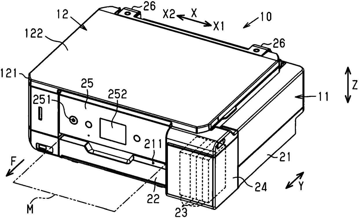
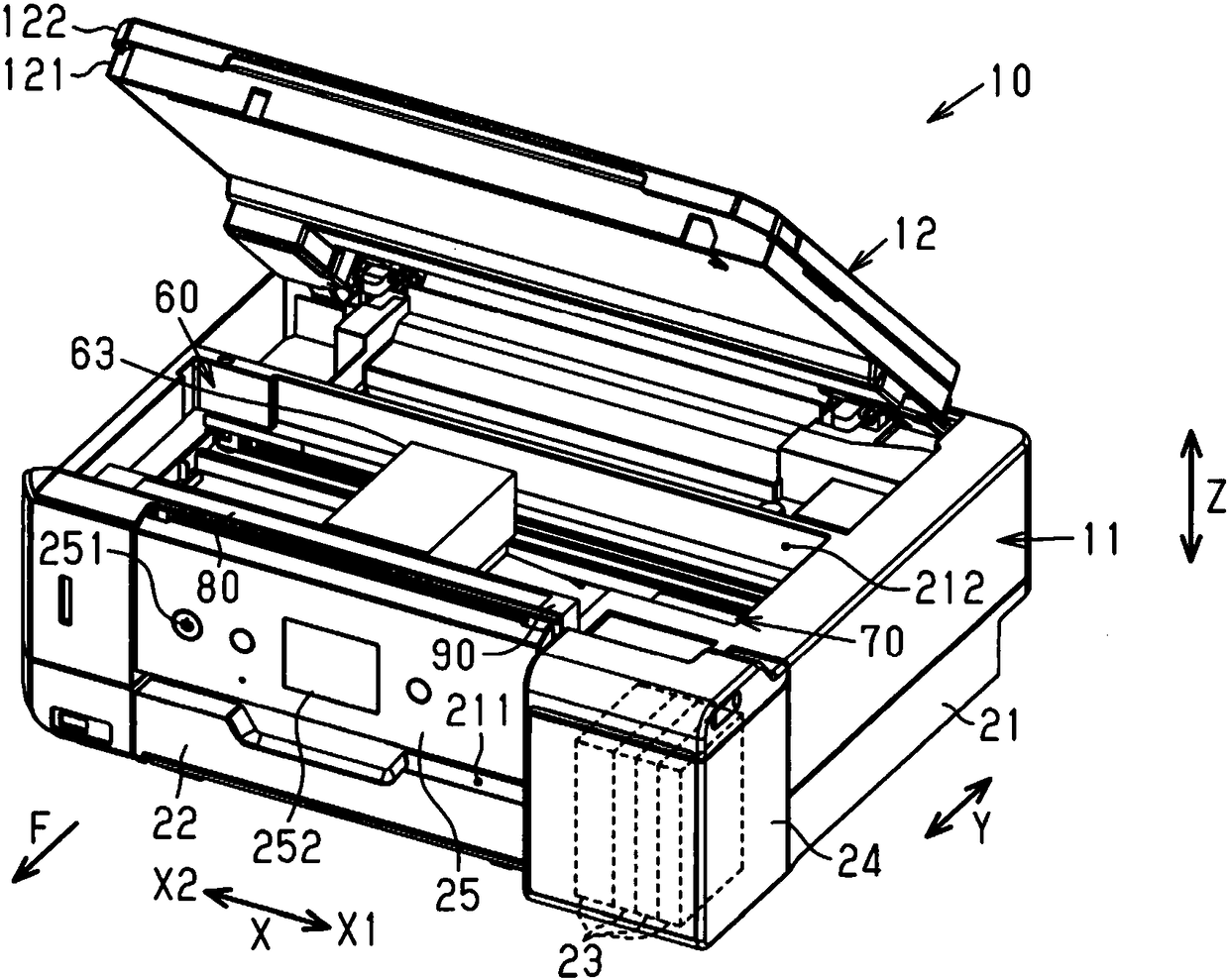
[0029] Such as figure 1 As shown, the multifunction peripheral 10 includes: a liquid ejecting device 11 that ejects liquid onto a medium M; and a reading device 12 that reads characters or images written on a document. In this embodiment, when the multifunction peripheral 10 is placed on a horizontal plane, the width direction of the multifunction peripheral 10 is referred to as the "scanning direction X", and the front and rear directions of...


PUM


Abstract

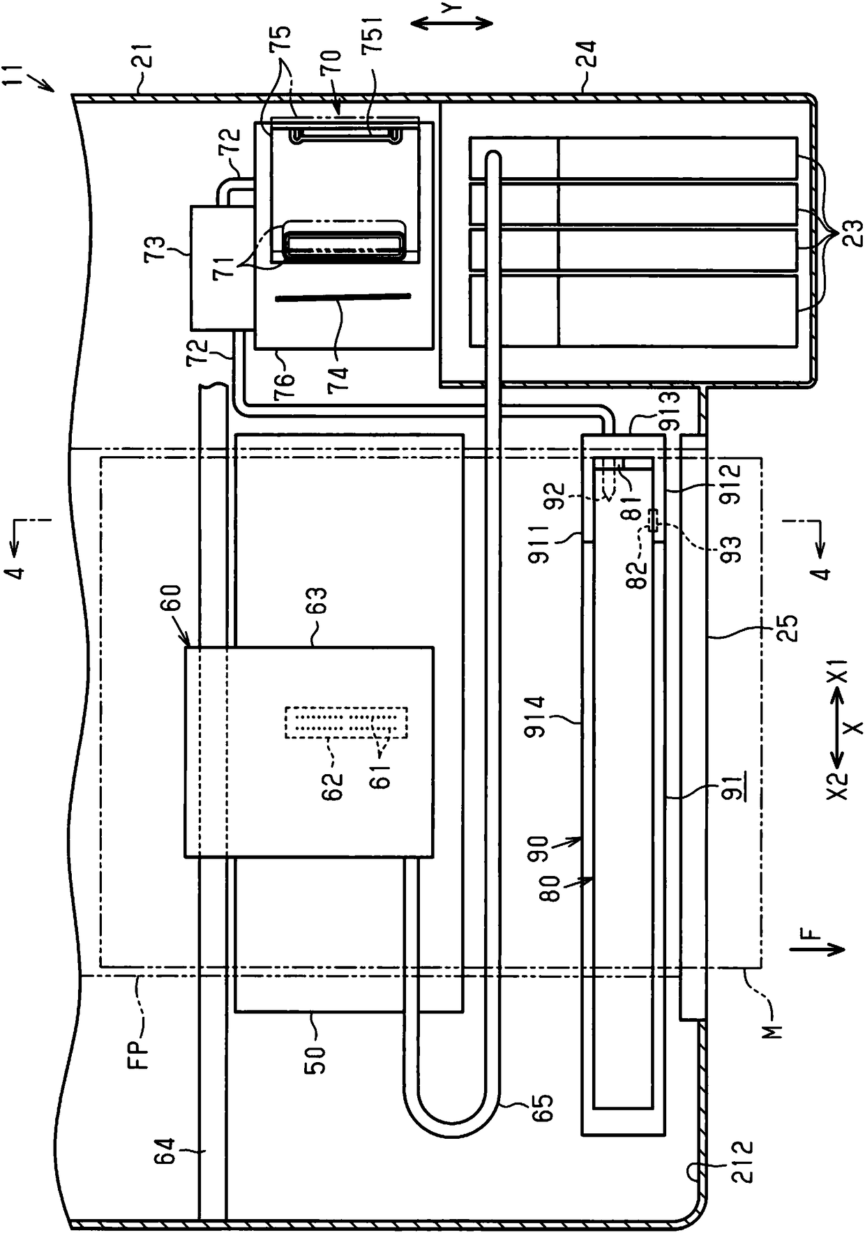
The invention provides a liquid spraying device which comprises a waste liquid storage body for storing waste liquid and is good in maintainability. The liquid spraying device (11) comprises a conveying part, a sliding rack (63), a liquid spraying head (62) and a keeping part (90). The conveying part conveys media (M) along the transmission direction (F). The sliding rack is arranged above the conveying path (FP) of the media (M) and is capable of carrying out reciprocating movement in the scanning direction (X) crossed with the conveying direction (F). The liquid spraying head is carried by the sliding rack (63) and sprays liquid towards the media (M) conveyed in the conveying direction (F). The keeping part is capable of keeping the waste liquid storage body (80) discharged from the liquid spraying head (62), is configured to be in the position which is higher than the conveying path (FP) and is closer to the downstream side in the conveying direction (F) compared with the moving path of the sliding rack (63).

Description

technical field [0001] The present invention relates to a liquid ejection device. Background technique [0002] Conventionally, a recording device is known as an example of a liquid ejecting device. The recording device includes: a transport unit that transports a recording medium; a recording unit that ejects ink to the recording medium; and a housing that It accommodates the transport unit and the recording unit. Among such recording devices, there is a device provided with a waste liquid absorbing member (waste liquid storage body) that absorbs ink waste liquid discharged from the recording unit during maintenance work (for example, Patent No. Literature 1). [0003] However, in the recording apparatus as described above, since the waste liquid absorbing member is disposed behind the recording unit, the maintainability of the waste liquid absorbing member tends to decrease. [0004] Patent Document 1: Japanese Patent Laid-Open No. 2006-35662 Contents of the invention...

Claims


Application Information

Patent Timeline
IPC IPC(8): B41J2/185
CPCB41J2/185
Inventor 小林努落合俊之
Owner SEIKO EPSON CORP
Learn More