Garbage can with internal automatic compacting function

A garbage can and automatic technology, applied in the direction of garbage cans, garbage collection, household appliances, etc., can solve the problems of garbage scattered on the ground, high frequency of replacement, knocked down garbage cans, etc., to achieve convenient garbage placement, good effect, and improved stability sexual effect

Active Publication Date: 2018-11-23
SHANDONG CHENNENG ENERGY TECH CO LTD
View PDF8 Cites 2 Cited by
  • Summary
  • Abstract
  • Description
  • Claims
  • Application Information

AI Technical Summary

Problems solved by technology

In the prior art, the indoor trash can is usually placed in a fixed position such as the kitchen or the living room. When pets are raised at home or when walking carelessly, the trash can is easily knocked down, and the garbage in the bucket is scattered on the ground; and the trash can is very It is easy to fill up when there is a large gap, resulting in a waste of resources, and at the same time, the frequency of replacement is high, which is very inconvenient

Method used


Image

  • Garbage can with internal automatic compacting function
  • Garbage can with internal automatic compacting function
  • Garbage can with internal automatic compacting function

Examples


Embodiment 1

[0032] The following is a description of Embodiment 1.

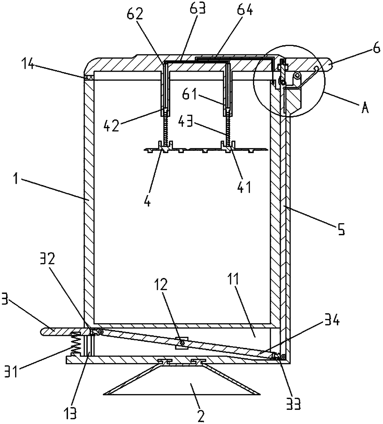
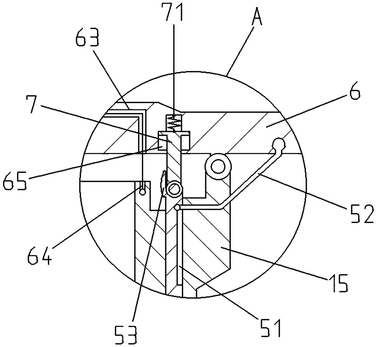
[0033] Such as Figure 1 to Figure 5 As shown in the figure, an internal automatic compression garbage can includes a barrel body 1, an installation cavity 11, a lever fulcrum 12, a stepping slide rail 13, a shockproof pad 14, a protective fulcrum block 15, a jack rod accommodation groove 16, and a bucket bottom plate 17 , bag installation groove 18, soft sucker 2, stepping plate 3, stepping spring 31, adaptive front sliding chamber 32, adaptive slider 33, start lever 34, adaptive rear sliding chamber 35, compacting plate 4, limiting Position slot 41, T-shaped slide bar 42, compaction spring 43, anti-skid protrusion 44, start ejector rod 5, rope body accommodation groove 51, pull cover rope 52, steel wire support block 53, protective cover 6, compaction positioning rod 61. Positioning sliding cavity 62, steel wire channel 63, tensioning steel wire 64, supporting sliding cavity 65, starting support rod 7, adaptive spring...

Embodiment 2

[0039] The following is a description of Embodiment 2.

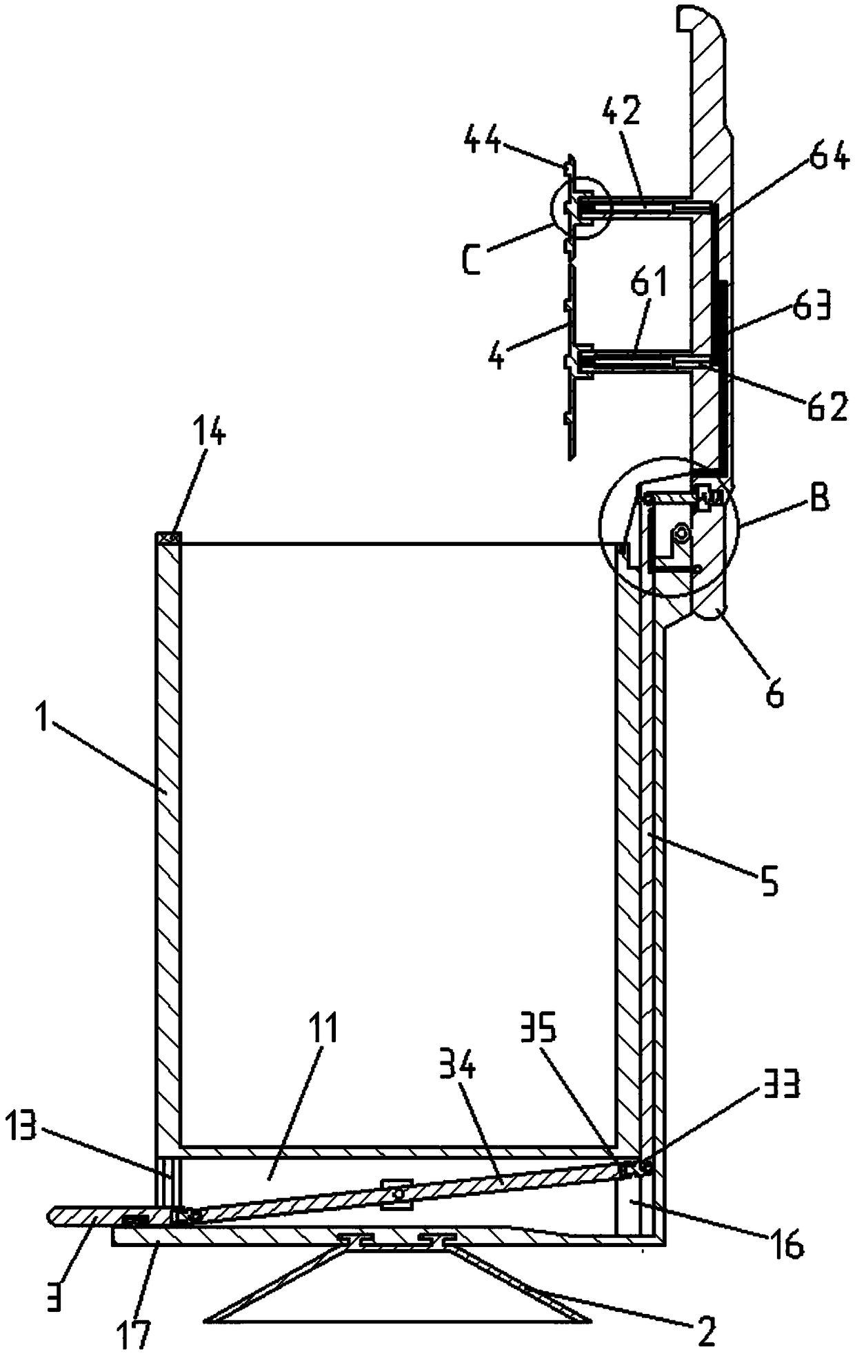
[0040] In embodiment 2, for the same structure as embodiment 1, give the same symbol, omit the same description, embodiment 2 has made improvement on the basis of embodiment 1, as Figure 6 As shown, the length of the compacting positioning rod 61 is reduced, the T-shaped sliding rod 42 adopts a telescopic rod 8, and the top rod body of the telescopic rod 8 is set in a T shape and is slidably arranged in the positioning sliding cavity 62, The tension steel wire 64 passes through the inside of the telescopic rod 8 and is connected with the top of the compacting plate 4 .

[0041] The advantage of this embodiment is that the shrinkage length of the compacting plate 4 can be made smaller, which facilitates opening the protective cover 6 and can more effectively adapt to the height of the garbage in the bucket body 1 .

[0042] When positioning the device, select the pre-fixed position of the trash can, and press the soft s...


PUM


Abstract

The invention relates to a garbage can with an internal automatic compacting function and belongs to the technical field of household goods. The garbage can comprises a can body, and a mounting chamber is formed in the bottom of the can body. An opening is formed in one side of the mounting chamber, and treading sliding rails are arranged on the two sides of the opening. A treading plate is arranged on the treading sliding rails in a sliding mode, and a treading spring is arranged between the treading plate and a can bottom plate arranged at the bottom of the mounting chamber. A lever fulcrumis arranged at the center of the inner part of the mounting chamber, and the lever fulcrum is provided with a starting lever in a shaft mode. The garbage can solves the problem that garbage in an existing garbage can is non-uniformly distributed, and has the advantages of being convenient to use and good in effect. The garbage can can be effectively positioned, and the garbage in the can can be automatically compacted. Meanwhile, the internal automatic-compacted garbage has an anti-odor effect.

Description

technical field [0001] The invention relates to an internal automatic compression garbage bin, which belongs to the technical field of household products. Background technique [0002] At present, trash cans play a very important role in our daily life, which can effectively improve indoor and outdoor cleanliness. In the prior art, the indoor trash can is usually placed in a fixed position such as the kitchen or the living room. When pets are raised at home or when walking carelessly, the trash can is easily knocked down, and the garbage in the bucket is scattered on the ground; and the trash can is very It is easy to fill up when there is a large gap, resulting in a waste of resources, and at the same time, the frequency of replacement is high, which is very inconvenient. [0003] Aiming at the above existing technical conditions, the applicant of the present invention has done a lot of repeated and beneficial explorations, and the final product has achieved effective resu...

Claims


Application Information

Patent Timeline
Patent Type & Authority Applications(China)
IPC IPC(8): B65F1/14B65F1/16B65F1/06
CPCB65F1/06B65F1/1405B65F1/141B65F1/16B65F2001/1653B65F2210/162
Inventor 孙绍飞林雪峰孙洪涛
Owner SHANDONG CHENNENG ENERGY TECH CO LTD
Why Eureka
Try Eureka