
Bobbin chucking apparatus

A clamping device and spool technology, applied in the directions of transportation and packaging, conveying filamentous materials, thin material handling, etc., can solve the problems of sliding rod interference, affecting the quality of fully wound coils, etc., and achieve yarn breakage improvement, The effect of increased durability

Inactive Publication Date: 2018-11-23
ILJIN A TECH
View PDF13 Cites 0 Cited by
  • Summary
  • Abstract
  • Description
  • Claims
  • Application Information

AI Technical Summary

Problems solved by technology

The balance of the creel may be disturbed by the movement of the slide bar, adversely affecting the quality of the fully wound coil

Method used


Image

  • Bobbin chucking apparatus
  • Bobbin chucking apparatus
  • Bobbin chucking apparatus

Examples


Embodiment Construction

[0025] Hereinafter, preferred embodiments of the present disclosure will be described in detail.

[0026] Various embodiments of the present disclosure may be embodied in various different ways and should not be construed as limited to the example embodiments set forth herein. Also, these example embodiments of the present disclosure are provided so that this disclosure will be thorough and complete and can convey the inventive concept of the present disclosure to those skilled in the art.

[0027] Also, in the drawings, the size or thickness of various components are exaggerated for brevity and clarity. Like references refer to like elements throughout. Further, it will be understood that when element A is referred to as being "connected to" element B, element A may be directly connected to element B, or intervening element C may be present and element A and element B are indirectly connected to each other.

[0028] The terminology used herein is for the purpose of describi...


PUM


Abstract

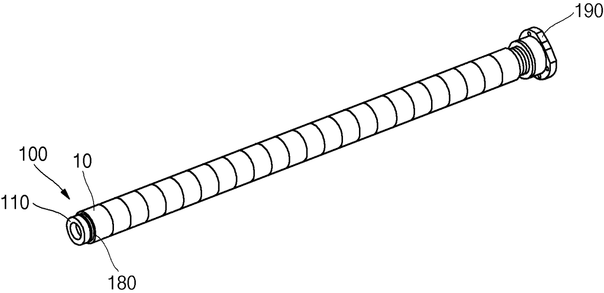
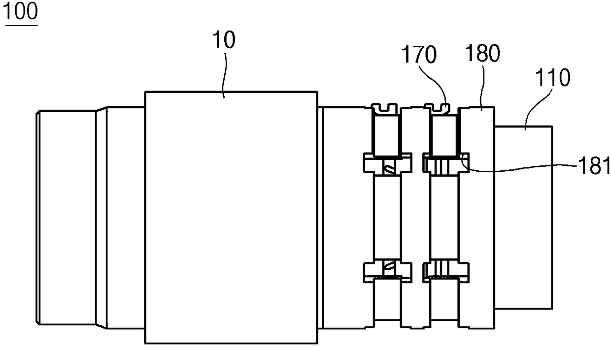
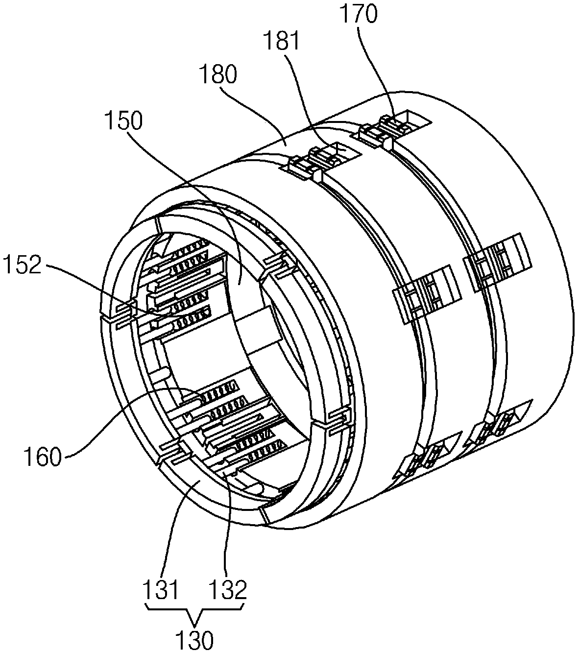
The present invention relates to a bobbin chucking apparatus for improving durability and improving quality of a fully wound cake. For example, disclosed is the bobbin chucking apparatus including: aholder for rotating a bobbin on which a yarn is wound; a coupling ring including a first fixed ring fixed to one side of the holder, a second fixed ring fixed to the remaining side of the holder, anda slide ring positioned between the first fixed ring and the second fixed ring and formed on an inner surface thereof with a plurality of coupling grooves; a spring accommodated in the coupling grooveto connect the first fixed ring to the slide ring; a piece mounted to the slide ring together with the second fixed ring to hold the bobbin; and a sleeve coupled to an outer side of the coupling ring, formed therein with a through-hole through which the piece passes, and coupled to the bobbin, wherein the slide ring is connected to the sleeve and movable in the horizontal direction.

Description

[0001] Cross References to Related Applications [0002] This application claims priority and benefit to Korean Patent Application No. 10-2017-0060604 filed with the Korean Intellectual Property Office on May 16, 2017, and all benefits obtained under 35 U.S.C. 119, the contents of which are hereby incorporated by reference in their entirety incorporated. technical field [0003] The present disclosure relates to spool gripping devices. Background technique [0004] A typical yarn winding device includes a creel that rotates to allow the yarn to be wound around the spool, and a clamping device for clamping the spool together with the creel to prevent the spool from wobbling. The clamping device includes a sliding rod, a sliding cone positioned in the creel, and a workpiece for clamping the spool, and is configured to clamp the spool using the elastic force of a spring. Furthermore, when the spool is intended to be withdrawn from the creel after the fully wound coil is wound...

Claims


Application Information

Patent Timeline
IPC IPC(8): B65H54/547
CPCB65H54/547B65H2701/31
Inventor 李善克金炅兑李哲京
Owner ILJIN A TECH
Learn More