

Synchrotron control method, device and storage medium
A synchrotron and control method technology, applied in radiation therapy, X-ray/γ-ray/particle irradiation therapy, treatment, etc., can solve the problem of high unplanned dose, reduce the time of radiotherapy, increase the dose rate of radiotherapy, and improve the effect of radiotherapy Effect
- Summary
- Abstract
- Description
- Claims
- Application Information
AI Technical Summary
Problems solved by technology
Method used
Image

Examples
Embodiment 1
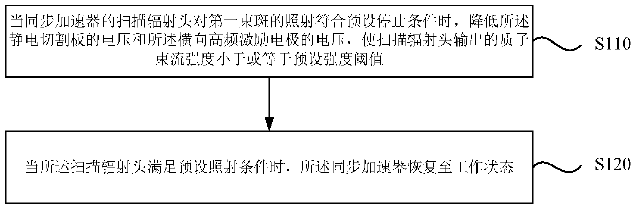
[0045] Figure 2a It is a flow chart of a synchrotron control method provided in Embodiment 1 of the present application. The technical solution of this embodiment is applicable to the situation of reducing the unplanned dose of radiation therapy, and this embodiment takes proton radiation therapy based on a synchrotron as an example for illustration. The method can be executed by the synchrotron control device provided in the embodiment of the present application, and the device can be implemented in at least one of the following ways: software and hardware, and the device is configured to be applied in a processor. The method comprises the steps of:
[0046] S110. When the irradiation of the first beam spot by the scanning radiation head of the synchrotron meets the preset stop condition, reduce the voltage of the electrostatic cutting plate and the voltage of the transverse high-frequency excitation electrode, so that the proton beam output by the scanning radiation head ...
Embodiment 2
[0063] image 3 It is a flow chart of the synchrotron control method provided by Embodiment 2 of the present application. The embodiment of the present application introduces real-time position detection on the basis of the above-mentioned embodiments, that is, discloses a synchrotron control method combined with real-time position detection. like image 3 As shown, the method includes:
[0064] S200. Detect the position of the first beam spot and the dose received by the first beam spot in real time.
[0065] The real-time position detection device detects in real time whether the position of the first beam spot is within the preset range, and detects whether the dose received by the first beam spot has reached the preset dose through the ionization chamber. The real-time position detection device may be respiratory gating, cone beam computed tomography (Cone beam Computed Tomography, CBCT), or other devices capable of real-time detection of tumor position changes, which i...
Embodiment 3
[0073] Figure 4 It is a structural block diagram of the synchrotron control device provided in the third embodiment of the present application. The device is configured to execute the synchrotron control method provided by any of the above embodiments, and the device may be implemented by software or hardware. The unit includes:
[0074] Stopping the beam output module 11 is configured to reduce the voltage of the electrostatic cutting plate and the voltage of the transverse high-frequency excitation electrode so that the output of the scanning radiation head The intensity of the proton beam is less than or equal to the preset intensity threshold;
[0075] Start the beam output module 12, which is set to restore the synchrotron to the working state when the scanning radiation head meets the preset irradiation conditions;
[0076] Wherein, the synchrotron includes the electrostatic cutting plate configured to deflect the proton beam, the transverse high-frequency excitation...
PUM
 Abstract
Description
Claims
Application Information