
Roller brush assembly and cleaning device with same

A cleaning device and roller brush technology, applied in the field of vacuum cleaners and roller brush components, can solve problems such as unclean cleaning

Pending Publication Date: 2018-11-27
SKYBEST ELECTRIC APPLIANCE SUZHOU CO LTD
View PDF0 Cites 9 Cited by
  • Summary
  • Abstract
  • Description
  • Claims
  • Application Information

AI Technical Summary

Problems solved by technology

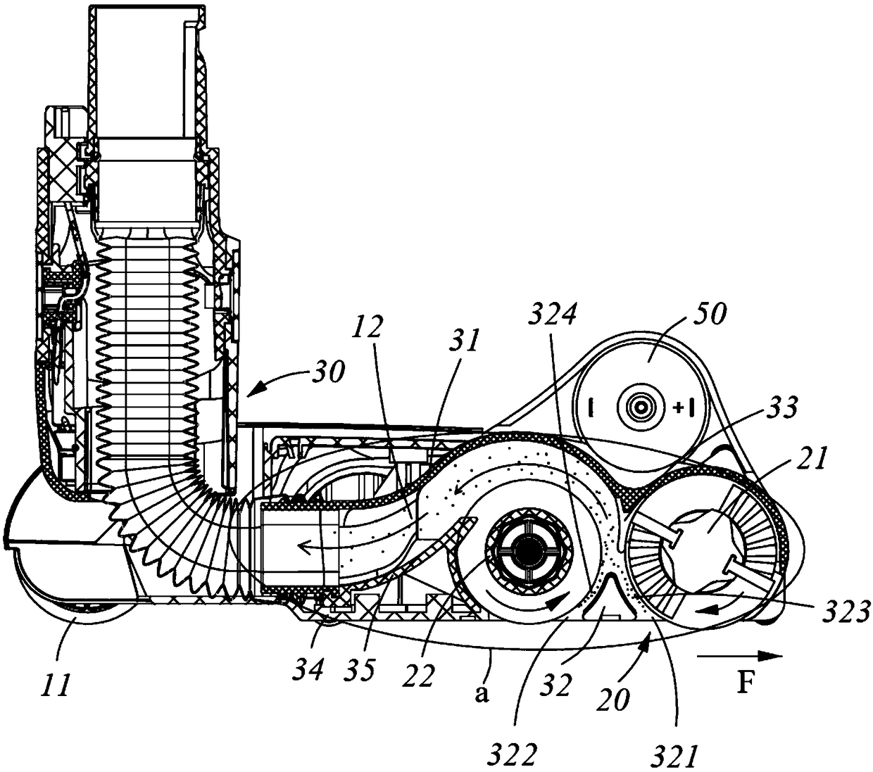
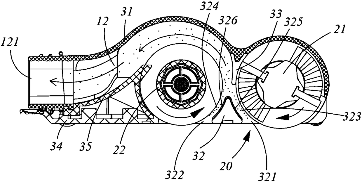
[0004] The common double roller brush floor brushes on the market are usually arranged in such a way that the fluff (soft bristles) are in front and the bristles (hard bristles) are in the back, so that it can clean the garbage backwards when it is working. , but often results in unclean cleaning

Method used


Image

  • Roller brush assembly and cleaning device with same
  • Roller brush assembly and cleaning device with same
  • Roller brush assembly and cleaning device with same

Examples


Embodiment Construction

[0028] The present invention will be described in detail below in conjunction with specific embodiments shown in the accompanying drawings. However, these embodiments do not limit the present invention, and any structural, method, or functional changes made by those skilled in the art according to these embodiments are included in the protection scope of the present invention.

[0029] It should be understood that terms such as "on", "above", "below", "below", etc. used herein to indicate relative spatial positions are for convenience of description to describe the relative position of an element or feature as shown in the drawings. A relationship to another element or feature. The terms of spatial relative position may be intended to encompass different orientations of the device in use or operation in addition to the orientation depicted in the figures.

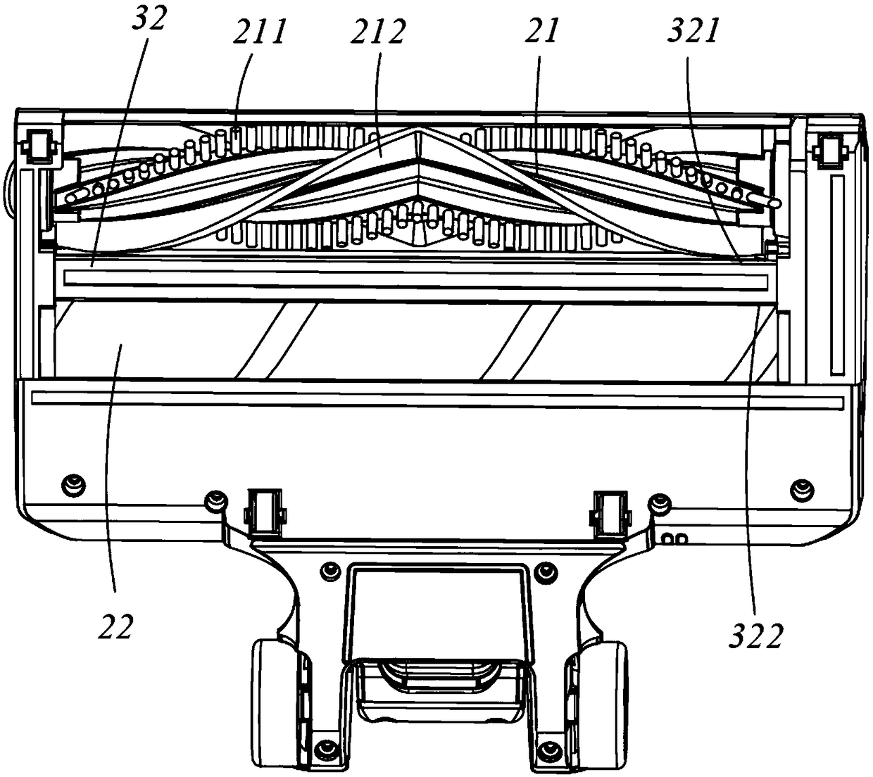
[0030] Such as Figure 1-4 As shown, preferred embodiments of the present invention are introduced. In this embodiment...


PUM


Abstract

The invention provides a roller brush assembly. The roller brush assembly comprises a first roller brush and a second roller brush disposed adjacently. The first roller brush is provided with first bristles, and the second roller brush is provided with second bristles. The first roller brush and the second roller brush are respectively rotated in opposite directions around the first axis and the second axis by a motor. Along the cleaning direction of the roller assembly, the first roller brush is in front, and the second roller brush is at the back. The hardness of the first bristles is largerthan that of the second bristles. By setting the roller brush assembly in the way that the hard bristles are in the front and the soft bristles are at the back, ground rubbish can be removed completely in the advancing process of the roller brush assembly.

Description

technical field [0001] The invention belongs to the technical field of cleaning appliances, and in particular relates to a rolling brush assembly for a vacuum cleaner and a vacuum cleaner with the same. Background technique [0002] A vacuum cleaner is a cleaning appliance used to remove dust from floors, carpets, walls, furniture, clothing and various crevices. Generally speaking, a vacuum cleaner mainly includes a suction device and a suction pipeline. The suction device mainly formed by a motor and a fan is arranged in the body of the vacuum cleaner. The suction pipeline includes a suction head, a suction pipe and a suction hose. The head has a suction port opening downwards and communicates with the air inlet of the fan inside the vacuum cleaner body through a dust suction pipe and a dust suction hose. [0003] The roller brushes of existing vacuum cleaners generally include two types, single roller brush and double roller brush. The rotation direction of the wheels is...

Claims


Application Information

Patent Timeline
IPC IPC(8): A47L9/04A47L9/00A47L9/10
CPCA47L9/00A47L9/04A47L9/0405A47L9/0411A47L9/102
Inventor 刘海平邢振宇于宇顾德志薛烨炜
Owner SKYBEST ELECTRIC APPLIANCE SUZHOU CO LTD
Learn More