
Integrated pneumatic device

A pneumatic and pneumatic technology, used in fluid pressure actuation devices, servo motor assemblies, mechanical equipment, etc., can solve the problems of many pipeline connection ends, high maintenance costs, complicated installation, etc., to achieve efficient use of space and simplification. Air connection, small size effect

Pending Publication Date: 2018-11-27
FOSHAN SAPFIT MACHINERY CO LTD +1
View PDF0 Cites 0 Cited by
  • Summary
  • Abstract
  • Description
  • Claims
  • Application Information

AI Technical Summary

Problems solved by technology

[0002] In the prior art, pneumatic devices generally use solenoid valves as the control core to drive cylinders to work, and each solenoid valve needs to be connected to the high-pressure gas of the external air pump through a pipeline, and must be equipped with components such as pressure regulating valves and mufflers. Separate fixed connection is required, the structure cost is high, the installation is complicated, there are many and messy pipe connection ends, it is easy to leak air, and the maintenance cost is high

Method used


Image

  • Integrated pneumatic device
  • Integrated pneumatic device
  • Integrated pneumatic device

Examples


Embodiment Construction

[0017] Embodiments of the present invention are described in detail below, examples of which are shown in the drawings, wherein the same or similar reference numerals designate the same or similar elements or elements having the same or similar functions throughout. The embodiments described below by referring to the figures are exemplary and are intended to explain the present invention and should not be construed as limiting the present invention.

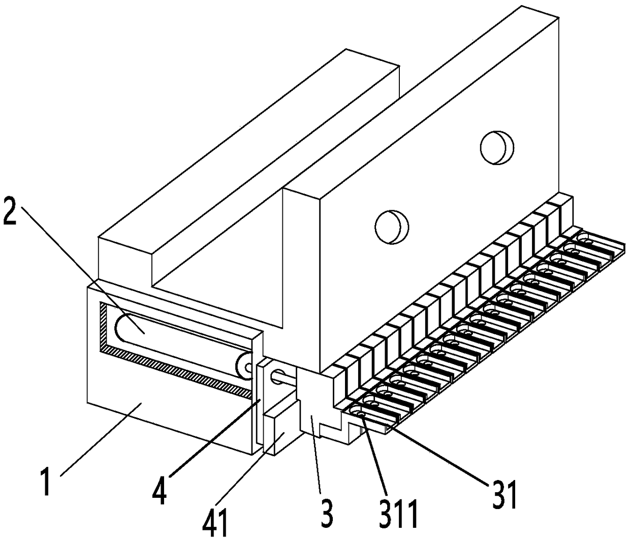
[0018] refer to figure 1 , an integrated pneumatic device, including a housing 1, and several metal pistons 2 installed in the housing 1, the front part of the housing 1 is provided with a telescopic part 3 connected with the metal piston 2, The housing 1 is provided with a baffle 4 between the metal piston 2 and the telescopic part 3, and an elastic part is connected to the end of the metal piston 2; the elastic part is preferably a spring, and the metal piston 2 passes through the Gas, exhaust and elastic parts cooperate to dr...


PUM


Abstract

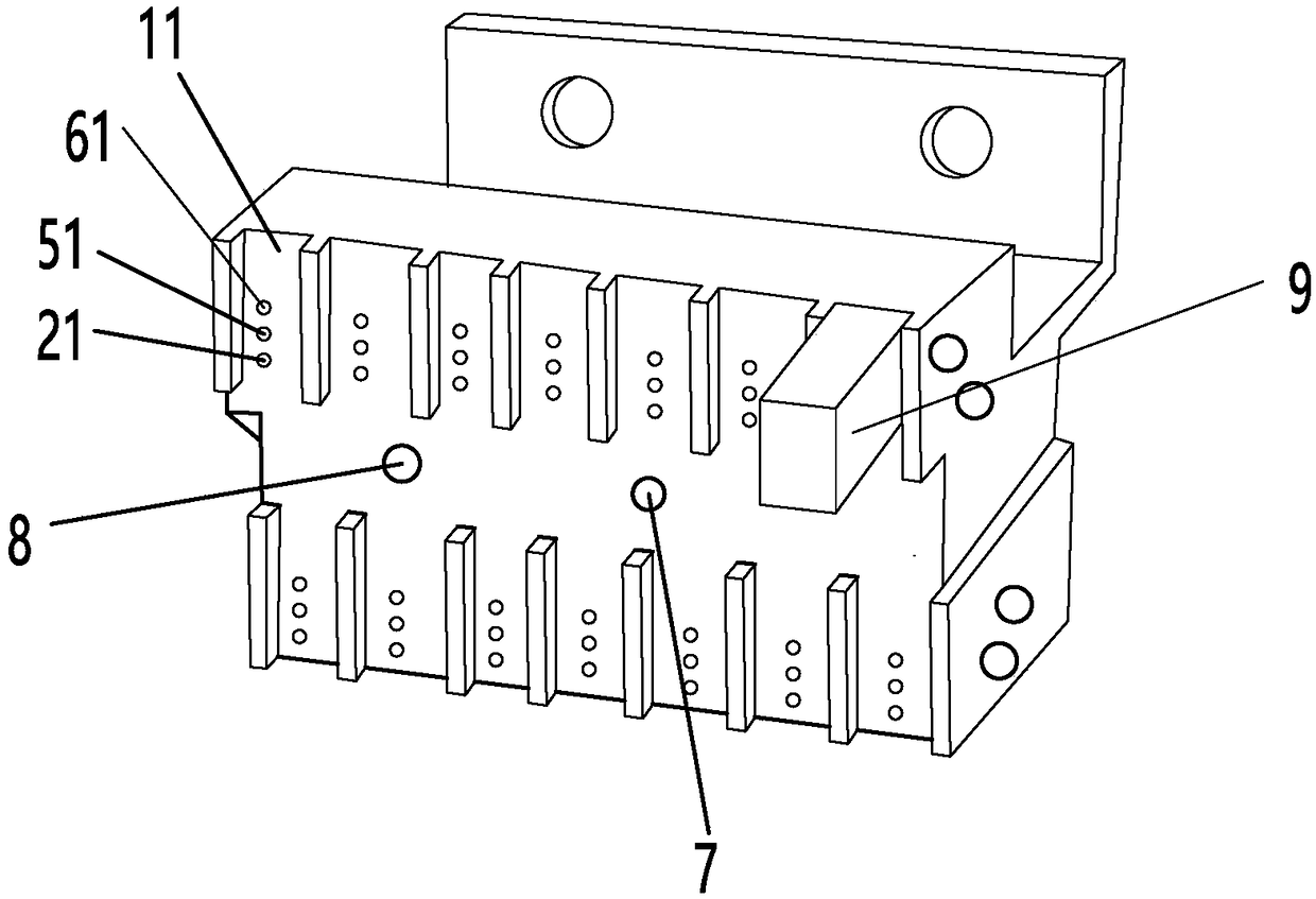
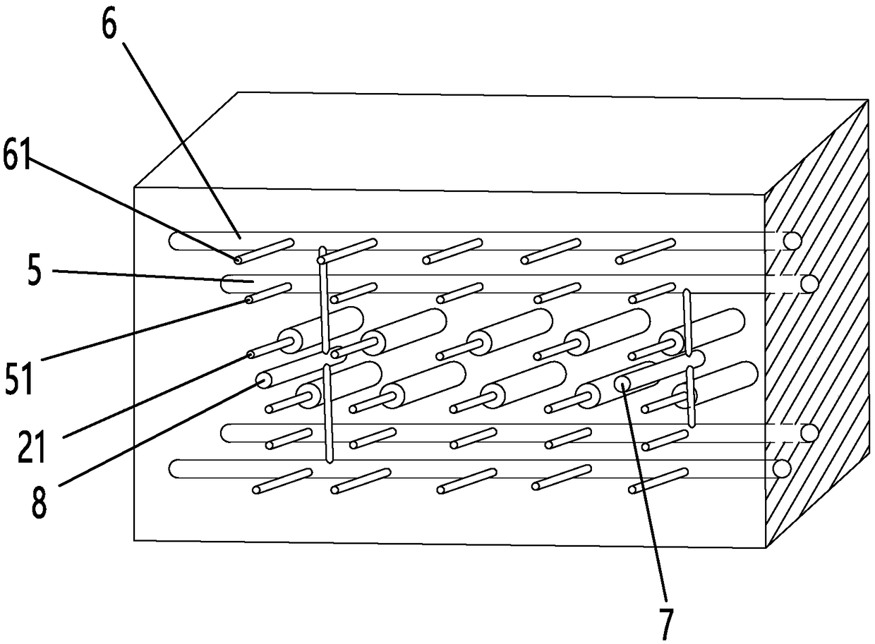
The invention discloses an integrated pneumatic device which comprises a housing and a plurality of metal pistons installed in the housing. The housing is provided with an airway channel, the airway channel comprises an air inlet channel and an air outlet channel, the housing is provided with multiple air inlets communicated with the air outlet channel, multiple air outlets communicated with the air outlet channels and multiple connecting ports communicated with the metal pistons, and the housing is also provided with a main air inlet communicated with the air inlet channel and a main air outlet communicated with the air outlet channel. The housing is also provided with multiple magnetic valves, and one magnetic valve controls closing of at least one air inlet, the air outlets and the connecting ports. The integrated pneumatic device achieves integration of the multiple metal pistons, completes independent work of the metal pistons through the unique airway structure and magnetic valves in the device, simplifies airway connection, is small in size and efficiently utilizes space position.

Description

technical field [0001] The invention relates to the field of pneumatic mechanical equipment, in particular to an integrated pneumatic device. Background technique [0002] In the prior art, pneumatic devices generally use solenoid valves as the control core to drive cylinders to work, and each solenoid valve needs to be connected to the high-pressure gas of the external air pump through a pipeline, and must be equipped with components such as pressure regulating valves and mufflers. Separate fixed connection is required, the structure cost is high, the installation is complicated, there are many and messy pipe connection ends, air leakage is very easy to occur, and the maintenance cost is high. Contents of the invention [0003] In order to overcome the deficiencies of the prior art, the invention provides an integrated pneumatic device with an optimized gas path structure and simplified pipeline connections. [0004] To achieve the above object, the technical scheme of t...

Claims


Application Information

Patent Timeline
Patent Type & Authority Applications(China)
IPC IPC(8): F15B15/14F15B13/08
CPCF15B13/0814F15B15/1404F15B15/1409
Inventor 陈锦杨学先邓伟丁有馀
Owner FOSHAN SAPFIT MACHINERY CO LTD
Learn More