Visual debugging method of invisible laser intrusion detector

A debugging method and detector technology, applied to instruments, alarms, etc., can solve problems such as inconvenience, inability to achieve precise alignment, and inability to accurately determine the center position of the laser optical axis, so as to improve efficiency and accuracy, and eliminate errors. the effect of

Pending Publication Date: 2018-11-27
广州市艾礼富电子科技有限公司
View PDF6 Cites 1 Cited by
  • Summary
  • Abstract
  • Description
  • Claims
  • Application Information

AI Technical Summary

Problems solved by technology

The laser seeker can only sense the existence of laser energy at a certain position, but it cannot accurately determine the center position of the optical axis of the laser. Therefore, the laser seeker can only help users find the laser beam emitted by the laser transmitter in a certain place. The approximate position of the laser detector helps the user to achieve the approximate alignment of the laser detector, but cannot help the user to achieve precise alignment; because the precise alignment of the laser beam of the laser transmitter and the receiving window of the laser receiver cannot be achieved, during the use of the laser intrusion detector In the process, due to environmental influences or changes, the detector will cause false alarms, which requires the user to repeatedly debug the beam alignment from time to time, which will bring a lot of inconvenience and confusion to the user.

Method used


Image

  • Visual debugging method of invisible laser intrusion detector

Examples


Embodiment Construction

[0015] The following will clearly and completely describe the technical solutions in the embodiments of the present invention with reference to the accompanying drawings in the embodiments of the present invention. Obviously, the described embodiments are only some, not all, embodiments of the present invention. Based on the embodiments of the present invention, all other embodiments obtained by persons of ordinary skill in the art without making creative efforts belong to the protection scope of the present invention.

[0016] The embodiment of the present invention discloses a visual debugging method of an invisible laser intrusion detector with the characteristics of visibility, precision, and high efficiency.

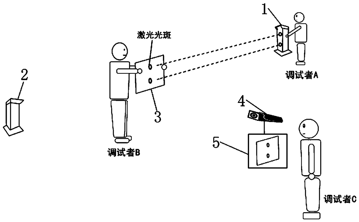
[0017] Please refer to the attached figure 1 , which is a visual debugging method of an invisible laser intrusion detector disclosed by the present invention, specifically includes:

[0018] The main equipment and tools used in this debugging method include: the la...


PUM


Abstract

The invention discloses a visual debugging method of an invisible laser intrusion detector. The visual debugging method is characterized that required main equipment and tools comprise a laser correlation emitter and a laser correlation receiver which form a laser intrusion detector, a paper board of which the area is slightly larger than that of the front surface of the laser correlation emitter,a black-white infrared camera, a display mated with the camera and field debugging staff A, B and C. By utilizing the visual debugging method of the invisible laser intrusion detector, disclosed by the invention, a user can be helped directly and clearly observe accurate positions of invisible laser beams emitted by a laser emitter of the laser intrusion detector during an installation and debugging or maintaining process of the laser intrusion detector, the user can be helped easily solve the problem that accurate alignment cannot be realized by the laser emitter and a laser receiver of thelaser intrusion detector, the efficiency and the accuracy of installation and debugging of the laser intrusion detector can be increased, and misinformation caused as accurate focusing cannot be realized by the laser intrusion detection in the past can be completely eradicated.

Description

technical field [0001] The invention relates to the technical field, and more specifically relates to a visual debugging method of an invisible laser intrusion detector. Background technique [0002] In order to achieve invisible protection for the target area, most laser intrusion detectors choose to use invisible laser as the light source of the detector; the invisible laser can be used to achieve invisible protection, making it difficult for intruders to evade, so as to achieve accurate alarm , the purpose of crime prevention; but using an invisible laser as a detector light source will also bring another kind of confusion to users, that is, how to achieve precise alignment and debugging of laser transmitters and laser receivers. The invisible laser intrusion detectors currently on the market all use laser seekers (laser locators) to determine the location of invisible laser beams. The working principle of the laser seeker (laser locator) is: the laser seeker has a rec...

Claims


Application Information

Patent Timeline
Patent Type & Authority Applications(China)
IPC IPC(8): G08B29/22
CPCG08B29/22
Inventor 陈盛友
Owner 广州市艾礼富电子科技有限公司
Why Eureka
Try Eureka