Mechanical peeling equipment for wire recycling

A mechanical and wire technology, applied in the field of mechanical peeling equipment for wire recycling, can solve the problems of low work efficiency and easy damage to the inner wires of the wire, and achieve the effect of convenient peeling

Active Publication Date: 2018-11-27
TIANCHANG TIANFENG MECHANICAL & ELECTRICAL TECH CO LTD
View PDF8 Cites 4 Cited by
  • Summary
  • Abstract
  • Description
  • Claims
  • Application Information

AI Technical Summary

Problems solved by technology

[0005] In order to overcome the disadvantages of low working efficiency and easy damage to the internal wires of electric wires in the prior art, the technical problem of the present invention is to provide a mechanical peeling device for electric wire recovery that has high working efficiency and will not damage the internal wires of electric wires

Method used


Image

  • Mechanical peeling equipment for wire recycling
  • Mechanical peeling equipment for wire recycling
  • Mechanical peeling equipment for wire recycling

Examples


Embodiment 1

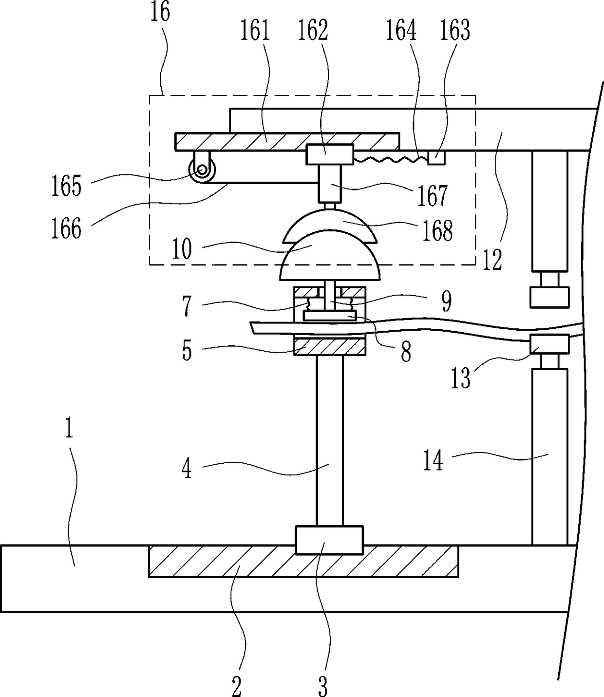
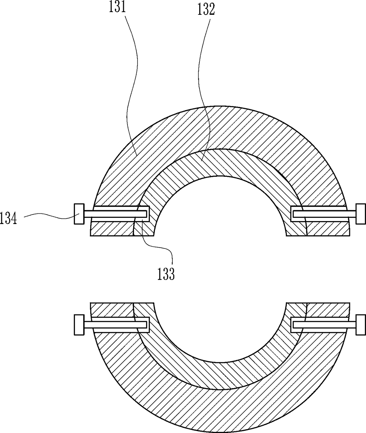
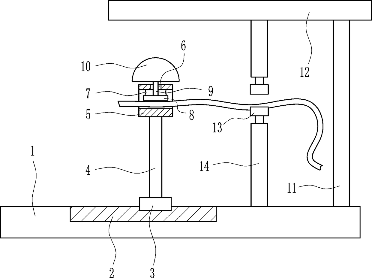
[0028] A mechanical peeling device for wire recycling, such as Figure 1-6As shown, it includes a bottom plate 1, a first slide rail 2, a first slider 3, a pole 4, a round tube 5, a first spring 7, a pressure plate 8, a guide rod 9, a protrusion 10, a bracket 11, a top plate 12, The cutting knife 13 and the first electric push rod 14, the first slide rail 2 is embedded on the left side of the top of the base plate 1, the first slide rail 2 is slidably provided with a first slide block 3, and the middle of the top of the first slide block 3 is provided with a support The rod 4 and the top of the pole 4 are provided with a round tube 5, the upper wall of the round tube 5 is provided with a guide hole 6, and the left and right sides of the upper inner wall of the round tube 5 are connected with the first spring 7, and the two first springs 7 are respectively located in the guide hole. On the left and right sides of 6, the bottom end of the first spring 7 is connected with a press...

Embodiment 2

[0030] A mechanical peeling device for wire recycling, such as Figure 1-6 As shown, it includes a bottom plate 1, a first slide rail 2, a first slider 3, a pole 4, a round tube 5, a first spring 7, a pressure plate 8, a guide rod 9, a protrusion 10, a bracket 11, a top plate 12, The cutting knife 13 and the first electric push rod 14, the first slide rail 2 is embedded on the left side of the top of the base plate 1, the first slide rail 2 is slidably provided with a first slide block 3, and the middle of the top of the first slide block 3 is provided with a support The rod 4 and the top of the pole 4 are provided with a round tube 5, the upper wall of the round tube 5 is provided with a guide hole 6, and the left and right sides of the upper inner wall of the round tube 5 are connected with the first spring 7, and the two first springs 7 are respectively located in the guide hole. On the left and right sides of 6, the bottom end of the first spring 7 is connected with a pres...

Embodiment 3

[0033] A mechanical peeling device for wire recycling, such as Figure 1-6 As shown, it includes a bottom plate 1, a first slide rail 2, a first slider 3, a pole 4, a round tube 5, a first spring 7, a pressure plate 8, a guide rod 9, a protrusion 10, a bracket 11, a top plate 12, The cutting knife 13 and the first electric push rod 14, the first slide rail 2 is embedded on the left side of the top of the base plate 1, the first slide rail 2 is slidably provided with a first slide block 3, and the middle of the top of the first slide block 3 is provided with a support The rod 4 and the top of the pole 4 are provided with a round tube 5, the upper wall of the round tube 5 is provided with a guide hole 6, and the left and right sides of the upper inner wall of the round tube 5 are connected with the first spring 7, and the two first springs 7 are respectively located in the guide hole. On the left and right sides of 6, the bottom end of the first spring 7 is connected with a pres...


PUM


Abstract

The invention relates to mechanical peeling equipment, and particularly relates to mechanical peeling equipment for wire recycling. The technical problem of the invention is to provide mechanical peeling equipment for wire recycling which is high in working efficiency and does not damage conductors inside wires. The mechanical peeling equipment for wire recycling comprises a bottom plate, a firstsliding rail, a first sliding block, a support rod, a circular tube, a first spring, a pressing plate and the like; the left side of the top of the bottom plate is embedded with the first sliding rail, the first sliding block is arranged in a sliding manner on the first sliding rail, the support rod is arranged at the middle of the top of the first sliding block, the circular tube is arranged on the top end of the support rod, the upper wall of the circular tube is provided with a guide hole, and the both the left side and the right side of the inner wall of the circular tube are connected with the first spring. The mechanical peeling equipment achieves the effects of being high in working efficiency and not damaging conductors inside wires. The mechanical peeling equipment is enabled to perform peeling on the wires easily through the cooperation of a bulge and a cutting knife.

Description

technical field [0001] The invention relates to a mechanical peeling device, in particular to a mechanical peeling device for electric wire recycling. Background technique [0002] The electric wire is composed of one or several soft wires, and the outside is wrapped with a light and soft sheath to conduct the carrier used by electric energy. [0003] Wires are more expensive and have a longer service life, so many manufacturers will recycle the wires and peel off the outer sheath of the wires for the second production and use. Now most of the wires are stripped manually, but the work efficiency of manual work is low, and it is easy to damage the inside of the wires of wires. [0004] To sum up, there is a need to develop a mechanical peeling device for wire recycling that has high work efficiency and will not damage the inner wires of the wires, so as to overcome the disadvantages of the prior art that it uses more labor, has low work efficiency, and is easy to damage the ...

Claims


Application Information

Patent Timeline
Patent Type & Authority Applications(China)
IPC IPC(8): H02G1/12
CPCH02G1/1256
Inventor 袁毅
Owner TIANCHANG TIANFENG MECHANICAL & ELECTRICAL TECH CO LTD
Why Eureka
Try Eureka