Vaporization assembly and electronic cigarette

a technology of electronic cigarettes and vaporization assembly, which is applied in the direction of ohmic-resistance heating, lighting and heating apparatus, tobacco, etc., can solve the problems of easy damage to electronic cigarettes, poor user experience, and short circuit in an entire circuit, so as to avoid heating temperature instability of electric heating wire assemblies, avoid health problems of users, and avoid peeling paint

Inactive Publication Date: 2017-10-19
HUIZHOU KIMREE TECH
View PDF9 Cites 55 Cited by
  • Summary
  • Abstract
  • Description
  • Claims
  • Application Information

AI Technical Summary

Benefits of technology

[0025]Applications of the vaporization assembly and an electronic cigarette of the present invention have following advantages: when the electronic cigarette is subjected to an impact or inclination for a long time, an additional arrange of an insulating tube to isolate the electric heating wire and the vaporization base for conducting electrical power for the electric heating wire to prevent the electric wire from being offset and in contact with the internal cavity of the vaporization base, then a resistance value connected into a circuit is changed can be avoided, thereby to avoid heating temperature instability of the electric heating wire assembly.
[0026]Moreover, the offset of the electric heating wire and the contact between the electric heating wire and the internal cavity of the vaporization base may cause an entire circuit to be short-circuited and then the control circuit board is directly damaged. By isolating with a method of the insulating tube, it is possible to avoid a problem of health of a user due to the fact that it is easy to suck peeling paint when the user is smoking, and it is easy to assemble and has a high production efficiency.
[0027]Further, the insulating tube is made of glass fibers so as to adsorb the e-liquid leaked or condensed on the smoke passage, and the user can be well prevented from inhaling the e-liquid, and the glass fibers has a characteristic of a high temperature resistance, thus, it is better to prevent the electric heating wire from burning the insulating tube, and it is possible to ensure the health of the user well; both the insulating tube and the annular projections on the vaporization base support the electric heating wire assembly axially to further protect the electric heating wire assembly to increase a stability of an electrical connection of the electric heating wire assembly;
[0028]Thus, the vaporization assembly of the present invention has a strong impact resistance, avoids a short circuit, has a long service life and an excellent user experience.

Problems solved by technology

However, the electric heating wire wound on the e-liquid guide is liable to be offset when it suffers impact or is inclined for a long time, then the electric heating wire may come to contact with an internal cavity of the vaporization base, resulting in a short circuit in an entire circuit and damage to a control circuit board.
This defect of the prior art makes the electronic cigarette easy to be damaged when the electronic cigarette is hit or fallen down, and the user experience is poor.

Method used


Image

  • Vaporization assembly and electronic cigarette
  • Vaporization assembly and electronic cigarette
  • Vaporization assembly and electronic cigarette

Examples


embodiment 1

FIGS. 1, 2, 3 and 4

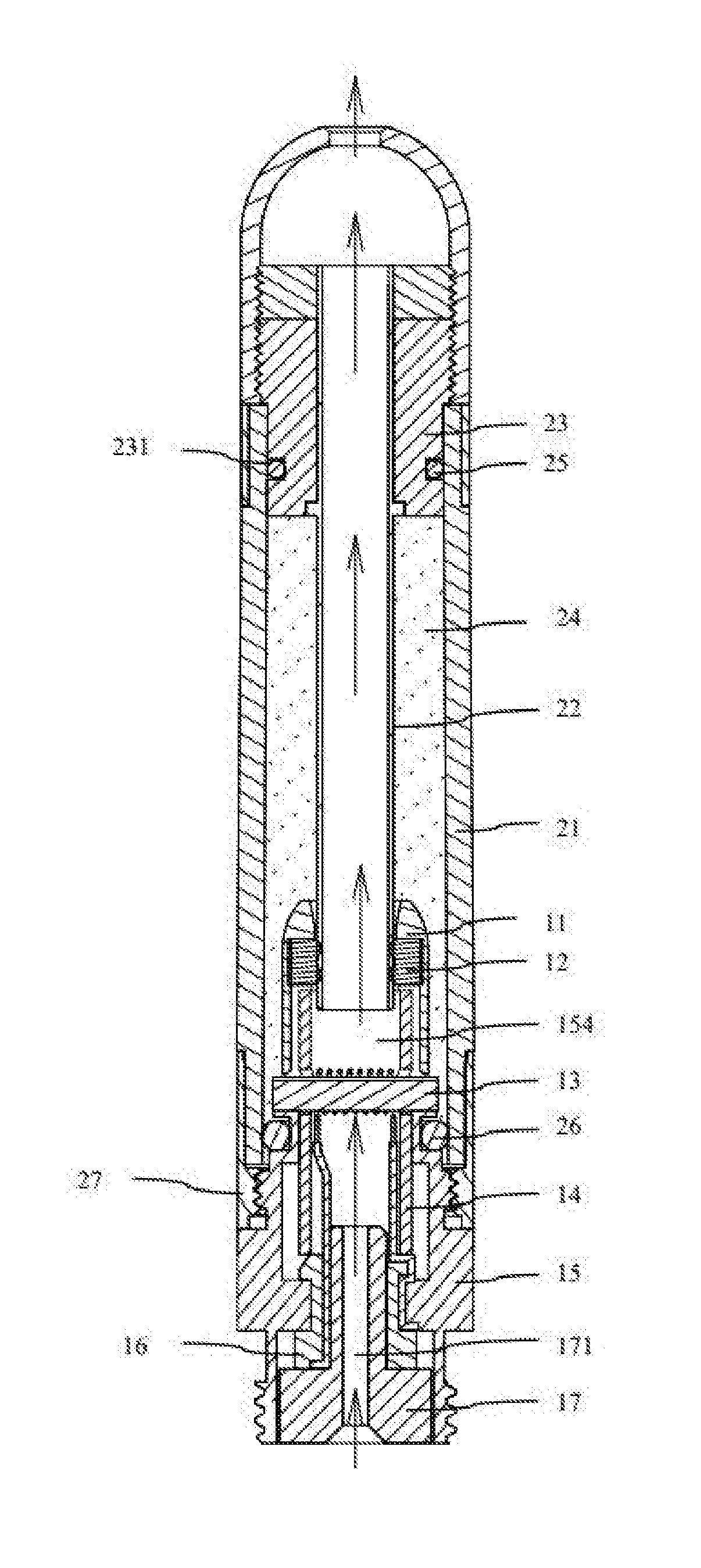
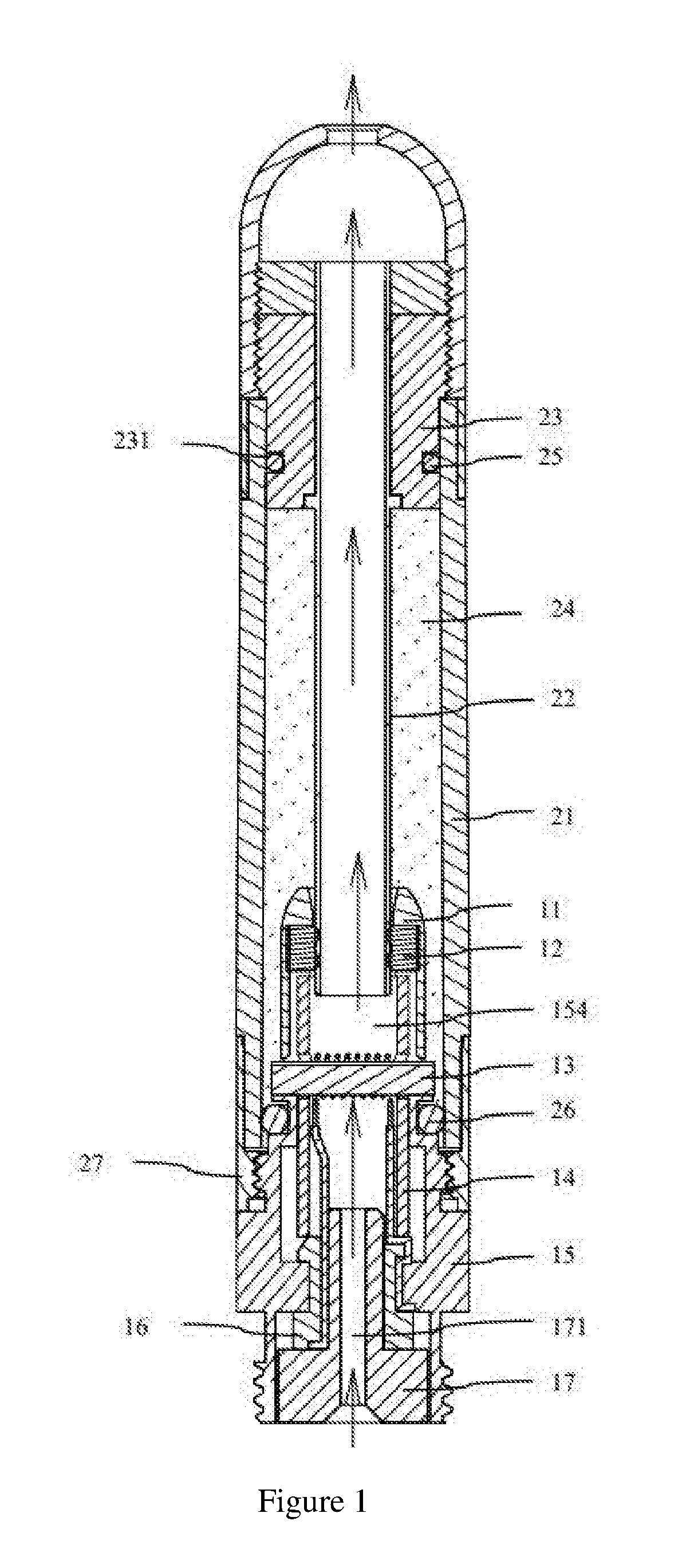
[0040]The vaporization assembly provided by the present invention comprises an e-liquid cup assembly and a vaporization core arranged in the e-liquid cup assembly, the e-liquid cup assembly comprises a vaporization sleeve 21, a vent pipe 22, an e-liquid separator 23 and a suction nozzle assembly, and the vaporization core, the vaporization sleeve 21, the vent pipe 22 and the e-liquid separator 23 surround to form an e-liquid storage chamber 24 for storing the e-liquid.

[0041]The vaporization sleeve 21 is a hollow tubular structure, one end of the vaporization sleeve 21 is detachably connected to the vaporization core through the connecting member 27, and the other end of the vaporization sleeve 21 is detachably connected to the e-liquid separator 23 and the suction nozzle assembly, respectively. In the present embodiment, the e-liquid separator 23 is inserted into an end of the vaporization sleeve 21 to avoid a leaking of the e-liquid, and the suction nozzle assemb...

embodiment 2

FIG. 5 with a Combination with FIGS. 1, 2 and 3

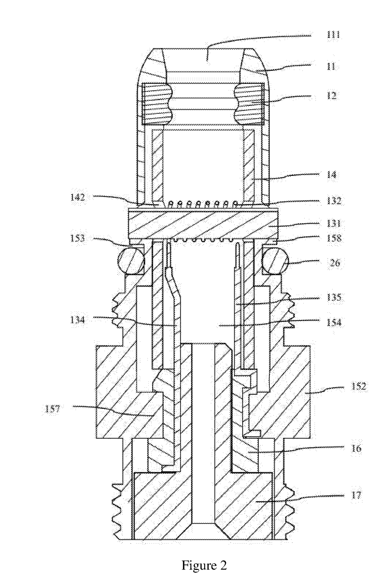
[0065]The present embodiment is different from Embodiment 1 in that the insulating tube 14 is defined coaxially with the internal cavity of the vaporization base 15, the cutout 141 extends from the fixing holes 142 to a side wall surface of the insulating tube 14, and a direction of the cutout 141 is perpendicular to an axial direction of the insulating tube 14, namely, the cutout 141 is defined horizontally.

embodiment 3

FIG. 6 with a Combination with FIGS. 1, 2 and 3

[0066]The present embodiment is different from the above embodiments in that the insulating tube 14 is defined coaxially with the internal cavity of the vaporization base 15, the cutout 141 extends from the fixing holes 142 to a side wall surface of the insulating tube 14, and a direction of the cutout 141 intersects with an axial direction of the insulating tube 14, namely, the cutout 141 is defined obliquely.


PUM


Abstract

The invention relates to a vaporization assembly and an electronic cigarette; the vaporization assembly comprises an e-liquid cup assembly and a vaporization core arranged in the e-liquid cup assembly; the e-liquid cup assembly has an e-liquid storage chamber used for accommodating e-liquid; the vaporization core comprises a vaporization base and an electric heating wire assembly; the vaporization base is internally provided with a smoke passageway used for providing passage to the smoke produced by vaporization; the electric heating wire assembly is arranged on the smoke passageway; the electric heating wire assembly comprises an electric heating wire used for heating and vaporizing the e-liquid; the vaporization core comprises an insulating tube used for isolating the vaporization base from the electric heating wire; the insulating tube is interposed in the vaporization base, and supports the electric heating wire along the length of the vaporization base.

Description

FIELD OF THE INVENTION[0001]The present application relates to a technical field of an electronic cigarette, and more particularly relates to a vaporization assembly and an electronic cigarette.BACKGROUND OF THE INVENTION[0002]In the prior arts, an electronic cigarette comprises a vaporization assembly and a battery assembly, the vaporization assembly comprises a vaporization sleeve for storing e-liquid and a vaporization core interposed in one end of the vaporization sleeve. The vaporization core is provided with a vaporization base made of a metal material, an internal electrode interposed at one end of the vaporization base, and an electric heating wire assembly for atomizing the e-liquid in the vaporization sleeve. Generally, the electric heating wire assembly is inserted laterally in a middle area of the vaporization base, and the internal electrode and one end of the vaporization base is generally used as electrodes for transferring electrical power to an electric heating wire...

Claims


Application Information

Patent Timeline
Patent Type & Authority Applications(United States)
IPC IPC(8): A24F47/00H05B3/44F22B1/28A24F40/10A24F40/40
CPCA24F47/008F22B1/284H05B3/44H05B2203/014H05B2203/021H05B2203/022A24F40/10A24F40/40
Inventor LIU, QIUMING
Owner HUIZHOU KIMREE TECH
Why Eureka
Try Eureka