Optical film composite having spatially controlled adhesive strength

a technology of optical film and adhesive strength, applied in the field of optical films, can solve the problems of reducing the application range of optical films, reducing the quality of optical films. , to achieve the effect of reducing the risk of premature delamination, improving handling and processing, and promoting adhesion

Inactive Publication Date: 2007-06-14
EASTMAN KODAK CO
View PDF15 Cites 59 Cited by
  • Summary
  • Abstract
  • Description
  • Claims
  • Application Information

AI Technical Summary

Benefits of technology

[0017] This invention overcomes the limitations of prior art optical films prepared by conventional casting methods and provides an improved optical film composite that is thinner and has improved handling and processing during the steps necessary for the fabrication of Liquid Crystal Displays. It also provides an improved optical film composite comprising an adhesive layer that promotes adhesion to PVA dichroic films that eliminates the need for complex surface treatments such as saponification prior to the fabrication of polarizer plates used in Liquid Crystal Displays. The invention also provides an improved optical film composite that reduces the risk of premature delamination of the optical film during manufacture of the composite while allowing easy peeling of the optical film during customer use. The cover sheet is less susceptible to physical damage such as scratch and abrasion and is more dimensionally stable during its manufacture, storage and final handling steps necessary in the fabrication of Liquid Crystal Displays. In addition, the optical film composite of the invention is less susceptible to defects due to dirt and abrasion during the manufacture of the optical film and polarizer plates.

Problems solved by technology

Because the stretched PVA films used to form polarizers are very fragile and dimensionally unstable, protective cover sheets are normally laminated to both sides of the PVA film to offer both support and abrasion resistance.
This saponification process is both messy and time consuming.
For many reasons, however, films prepared by melt extrusion are generally not suitable for optical applications.
In the case of highly substituted cellulose acetate, there is the additional problem of melting the polymer.
For these reasons, melt extrusion methods are generally not practical for fabricating many resin films including cellulose triacetate films used to prepare protective covers and substrates in electronic displays.
In general, thin films of less than 40 microns are very difficult to produce by casting methods due to the fragility of wet film during the peeling and drying processes.
Films having a thickness of greater than 200 microns are also problematic to manufacture due to difficulties associated with the removal of solvent in the final drying step.
Birefringence in cast or coated films arises from orientation of polymers during the manufacturing operations.
These shear forces orient the polymer molecules and ultimately give rise to undesirably high birefringence or retardation values.
Another drawback to the casting method is the inability to accurately apply multiple layers.
As noted in U.S. Pat. No. 5,256,357 to Hayward, conventional multi-slot casting dies create unacceptably non-uniform films.
In particular, line and streak non-uniformity is greater than 5% with prior art devices.
Acceptable two layer films may be prepared by employing special die lip designs as taught in U.S. Pat. No. 5,256,357 to Hayward, but the die designs are complex and may be impractical for applying more than two layers simultaneously.
Another drawback to the casting method is the restrictions on the viscosity of the dope.
At these high viscosity values, however, casting dopes are difficult to filter and degas.
While fibers and larger debris may be removed, softer materials such as polymer slugs are more difficult to filter at the high pressures found in dope delivery systems.
Particulate and bubble artifacts create conspicuous inclusion defects as well as streaks and may create substantial waste.
In addition, the casting method can be relatively inflexible with respect to product changes.
Because casting requires high viscosity dopes, changing product formulations requires extensive down time for cleaning delivery systems to eliminate the possibility of contamination.
Particularly problematic are formulation changes involving incompatible polymers and solvents.
In fact, formulation changes are so time consuming and expensive with the casting method that most production machines are dedicated exclusively to producing only one film type.
If the peelable film is only weakly adhered to the carrier substrate, the film may be prone to premature delamination from the carrier substrate during its manufacture or during subsequent coating steps.
This may thus result in a reduction in the efficiency of the manufacturing / coating facility.

Method used


Image

  • Optical film composite having spatially controlled adhesive strength
  • Optical film composite having spatially controlled adhesive strength
  • Optical film composite having spatially controlled adhesive strength

Examples


example 2 (

Invention)

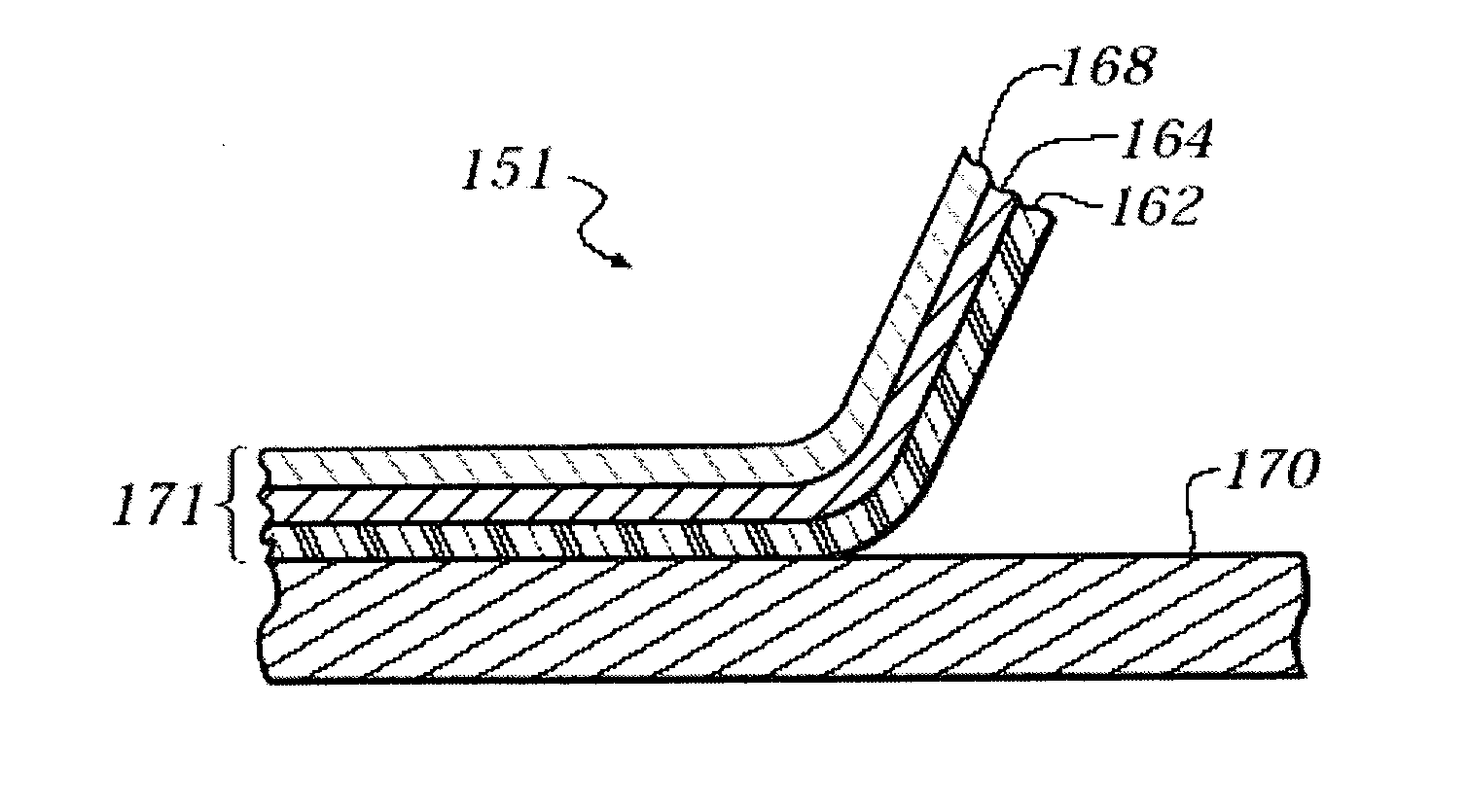
[0160] A second optical film composite was produced in a manner similar to Example 1 with the exception that the peelable layer was coated at a width of 1,283 mm. The corona discharge treatment applied across the full width of the peelable layer and temporary carrier substrate was 5.2 kJ / m2. As in the case of the optical film composite in Example 1, the width of the triacetyl cellulose optical film coating was 1,308 mm, thus creating an edge area in the case of Example 2 that was 12.5 mm wide on each lateral edge of the carrier substrate. These edge areas, taken together, constitute 1.8% of the area of the carrier substrate. The adhesive strength of the optical film to the carrier substrate in the center area of the optical film composite was found to be 0.6 N / m. The adhesive strength of the optical film to the carrier substrate in the edge area of the optical film composite was found to be greater than 20 times the adhesive strength in the center area.

[0161] The method u...


PUM

PropertyMeasurementUnit
lengthaaaaaaaaaa
thickaaaaaaaaaa
melting temperatureaaaaaaaaaa

Abstract

The present invention generally relates to optical films useful in the manufacture of polarizer plates, an improved method for producing polarizing plates, and a Liquid Crystal Display employing the same. More particularly, the invention relates to an optical film composite comprising a temporary carrier substrate having a center area and an edge area, said substrate having coated thereon an optical film wherein the adhesive strength between the optical film and the substrate is greater at the edge area than at the center area of the substrate.

Description

FIELD OF THE INVENTION [0001] The present invention generally relates to optical films useful in the manufacture of polarizer plates, an improved method for producing polarizing plates, and a Liquid Crystal Display employing the same. It particularly relates to protective cover sheets for use with polarizer plates. BACKGROUND OF THE INVENTION [0002] Transparent resin films are used in a variety of optical and display applications. In particular, resin films are used as protective cover sheets for light polarizers in a variety of electronic displays, particularly Liquid Crystal Displays (LCD). [0003] LCDs contain a number of optical elements that may be formed from resin films. The structure of reflective LCD's may include a liquid crystal cell, one or more polarizer plates, and one or more light management films. Liquid crystal cells are formed by dispersing liquid crystals such as twisted nematic (TN) or super twisted nematic (STN) materials between two electrode substrates. Polari...

Claims


Application Information

Patent Timeline
Patent Type & Authority Applications(United States)
IPC IPC(8): B32B33/00
CPCB32B37/00B32B38/0008B32B2037/243B32B2307/42B32B2310/14B32B2457/20B32B2457/202Y10S428/906Y02P20/582Y10T428/1481Y10T428/24793Y10T428/14Y10T428/24777Y10T428/24942G02B1/16G02B1/14
Inventor HUBERT, TIMOTHYGROS, ALAINSCHULTZ, RALPHWANG, YONGCAILEI, HERONGCHEN, WEN-LIANDERSON, CHARLES
Owner EASTMAN KODAK CO
Why Eureka
Try Eureka