Static var generator (SVG)-based charged ice melting topology system and ice melting method thereof

An ice-melting method and topology technology, applied in electrical components, cable installation, overhead line/cable equipment, etc., can solve the problems of high line structure requirements, system instability, large system consumption, etc., and achieve the effect of increasing the transmission flow

Inactive Publication Date: 2018-11-27
STATE GRID HUNAN ELECTRIC POWER +2
View PDF5 Cites 8 Cited by
  • Summary
  • Abstract
  • Description
  • Claims
  • Application Information

AI Technical Summary

Problems solved by technology

Among them, the live ice-melting topology system based on the unified power flow controller consumes a lot of energy and easily leads to system instability; the live-line ice-melting topology structure based on double-circuit lines between substations has high requirements on the line structure and narrow application range; based on load c

Method used


Image

  • Static var generator (SVG)-based charged ice melting topology system and ice melting method thereof

Examples


Embodiment 1

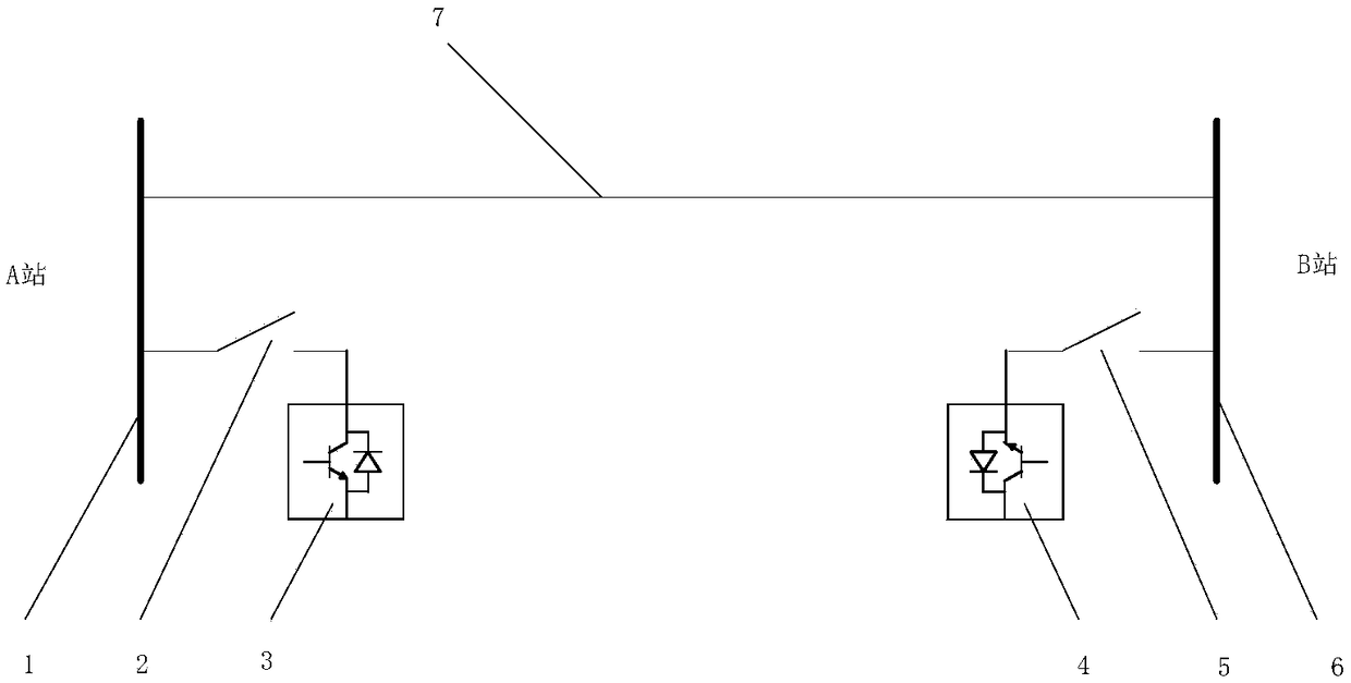
[0026] like figure 1 As shown, the SVG-based electrified ice-melting topology system of this embodiment includes a power transmission line 7 connected in series between the bus bar of the first substation 1 and the bus bar of the second substation 6, and is characterized in that it also includes The first SVG device 3 is serially connected to the busbar of the first substation 1 , and the second SVG device 4 is serially connected to the busbar of the second substation 6 through the second switch 5 .

[0027] The charged ice-melting topology system is equipped with SVG devices at both ends of the transmission line. By setting the SVG working mode, a structure in which one end emits reactive power and the other end absorbs reactive power is formed to increase the transmission flow of the line to achieve heat melting. The purpose of ice is to maintain the grid voltage unchanged at the same time, so that the user's electricity consumption will not be affected, and the ice melting ...

Embodiment 2

[0032] Corresponding to the above embodiments, this embodiment provides a method for melting ice, including the following steps:

[0033] S1: Detect the icing situation on the power transmission line 7, and adjust the gears of the first SVG device 3 and the second SVG device 4 to the set gear when the icing value on the power transmission line 7 is greater than or equal to the icing warning value ;

[0034] S2: Set one of the first SVG device 3 and the second SVG device 4 as a reactive power sending mode, and set the other as a reactive power receiving mode;

[0035] S3: closing the first switch 2 and the second switch 5, forming a current loop flowing among the first SVG device 3, the first switch 2, the power transmission line 7, the second switch 5, and the second SVG device 4;

[0036] S4: Adjust the gears of the first SVG device 3 and the second SVG device 4 until the ice on the transmission line falls off, and then turn off the first switch 2 and the second switch 5 . ...


PUM


Abstract

The invention relates to the technical field of electrical engineering, and discloses a static var generator (SVG)-based charged ice melting topology system and an ice melting method thereof, aiming at forming a structure which emits reactive power at one end and absorbs the reactive power at the other end so as to increase the transmission trend of a circuit and achieve the purpose of heating formelting ice; furthermore, the grid voltage is maintained to be unchanged, the electricity use of a user is not affected, and charged ice melting is realized. The charged ice melting topology system comprises an electric transmission line which is in series connection between a first substation bus and a second substation bus; the charged ice melting topology system comprises a first SVG device and a second SVG device, wherein the first SVG device is connected with the first substation bus in series by means of a first switch, and the second SVG device is connected with the second substation bus in series by means of a second switch.

Description

technical field [0001] The invention relates to the technical field of electrical engineering, in particular to an SVG-based electrified ice-melting topology system and an ice-melting method. Background technique [0002] In recent years, rain, snow and freezing disasters have occurred frequently in the southern region, which has seriously affected the operation of the power grid. Current ice melting is currently the most direct and effective measure to deal with power grid ice disasters. However, the existing ice melting methods are mainly based on power outages. On the one hand, a large number of users will be cut off after a power outage, which will affect the quality service of the power supply company and affect people’s daily life; on the other hand, when multiple lines When the line needs to melt ice, in order to ensure the safety of power supply, the power cannot be cut off at the same time to melt the ice, and it must be carried out sequentially, so that the ice is ...

Claims


Application Information

Patent Timeline
IPC IPC(8): H02G7/16H02G1/02
Inventor 陆佳政朱远李波谭艳军朱思国黄清军毛新果
Owner STATE GRID HUNAN ELECTRIC POWER
Why Eureka
Try Eureka