Miniature circuit breaker level relative inserting wire inletting structure

A miniature circuit breaker, horizontal technology, applied in the direction of busbar/line layout, protective switch terminal/connection, etc., can solve the problems of confusing wiring, high manufacturing cost, large space occupation, etc., to achieve convenient disassembly and maintenance, ensure electrical conductivity, Guaranteed overall effect

Active Publication Date: 2014-07-09
王卫庆
View PDF5 Cites 0 Cited by
  • Summary
  • Abstract
  • Description
  • Claims
  • Application Information

AI Technical Summary

Problems solved by technology

[0003] The purpose of the present invention is to provide a micro circuit breaker horizontally inserted into the incoming line structure to solve the problem of large space occupation and chaotic wiring in the prior art; when a certain circuit breaker needs to be replaced, the bus power supply needs to be disconnected, which affects the normal operation of other circuits Power supply; disassembly and maintenance are troublesome; the configuration of a certain distribution box requires a single customization, high manufacturing cost, poor interchangeability, and high cost of use; and the connection between the wire and the busbar needs to be drilled and connected with screws, which damages the overall busbar The structure and electrical conductivity, the problem of inconvenient connection

Method used


Image

  • Miniature circuit breaker level relative inserting wire inletting structure
  • Miniature circuit breaker level relative inserting wire inletting structure
  • Miniature circuit breaker level relative inserting wire inletting structure

Examples


Embodiment Construction

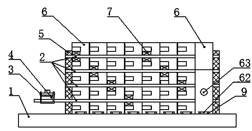
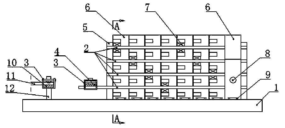
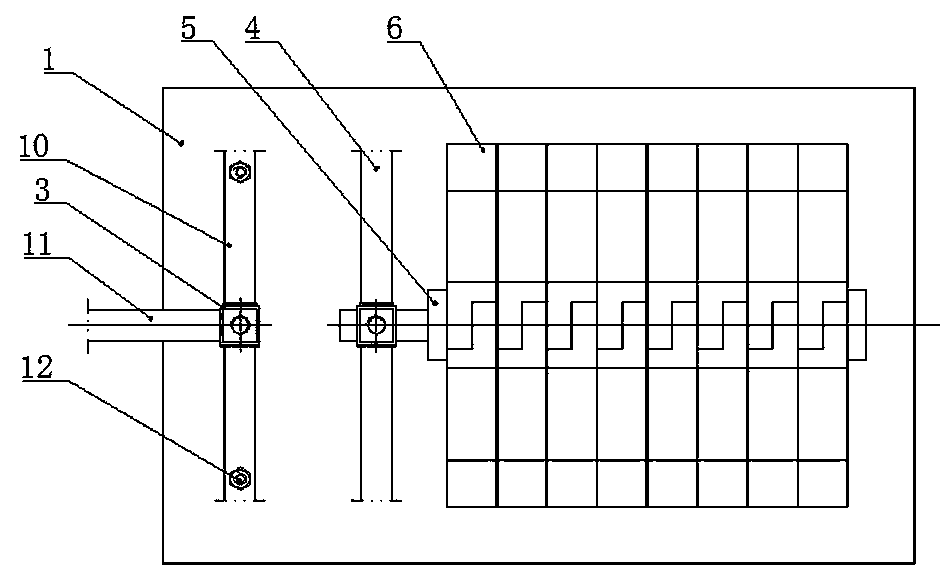
[0043] see Figure 1 to Figure 31 , the present invention is a miniature circuit breaker horizontally relatively inserted into the incoming line structure, including a miniature circuit breaker 6 and a busbar 2, and a plurality of busbars 2 are arranged side by side in multiple layers and fixed on the bottom plate 1 through an insulating bracket 5. The half of one end of the miniature circuit breaker 6 is provided with a plurality of rectangular teeth 61 corresponding to multiple busbars, and in the groove between a certain pair of rectangular teeth 61, there is an insertion port as the incoming line end of the miniature circuit breaker 6 . Type busbar conductive chuck 7, and the other end of the miniature circuit breaker 6 is provided with an outlet terminal 63 (conventional terminal). One end of the rectangular tooth 61 of the paired miniature circuit breaker 6 is plugged on both sides of the busbar 2, and the plug-in busbar conductive clip 7 of each miniature circuit breake...


PUM


Abstract

The invention provides a miniature circuit breaker level relative inserting wire inletting structure which comprises a miniature circuit breaker and busbars. Half of the one end of the miniature circuit breaker is provided with a plurality of rectangular teeth which correspond to the busbars, a plug-in busbar conductive clamping head of the wire inletting end of the miniature circuit breaker is arranged in a groove which is formed between a certain pair of rectangular teeth; one ends of the pairs of rectangular teeth of the miniature circuit breaker are connected at the two sides of the busbars in a relative and inserted mode, each plug-in busbar conductive clamping head of the miniature circuit breaker is connected to one busbar in a clamped mode, and the rectangular teeth at the half of a miniature circuit breaker is matched with the rectangular teeth at the half of another miniature circuit breaker in relatively inserted mode. Terminal distribution boxes produced through the connection mode of the circuit breaker can be precast and produced according to the standard series, and a box body, a guide rail, a wire inletting busbar and a zero busbar can be preset and integrated. Users only needs to design the loop number and switch capacity according to demands of the users and insert the switches into the system in sequence, and the final assembly is completed, dismantling and maintenance are greatly facilitated, and standard, high efficiency and low cost can be achieved.

Description

technical field [0001] The invention relates to a micro circuit breaker horizontally relatively inserted into the incoming line structure, which is mainly used for the electrical connection between the micro circuit breaker and the bus bar, through the plug-in bus bar conductive connector and through the guide rail to relatively horizontally insert into the bus bar to complete the conductive connection . It can be used to manufacture modularized and pre-installed terminal distribution boxes. Background technique [0002] The connection structure between the miniature circuit breaker and the bus bar in the prior art distribution box is that the two are connected to each other through wires, which has the disadvantage of taking up a large space and confusing wiring; when a certain circuit breaker needs to be replaced, the bus power supply needs to be disconnected, Affect the normal power supply of the rest of the circuit; disassembly and maintenance are troublesome; the confi...

Claims


Application Information

Patent Timeline
IPC IPC(8): H01H71/08H02B1/20
Inventor 王卫庆
Owner 王卫庆
Why Eureka
Try Eureka