Injection-molded part forming method requiring two stages of core pulling

A molding method and injection molding technology, applied in the field of injection molds, can solve the problems of easy interference and complex mold structure, and achieve the effect of convenient connection and reliable core pulling steps.

Active Publication Date: 2017-08-04
SHENTONG TECH GRP CO LTD
View PDF6 Cites 14 Cited by
  • Summary
  • Abstract
  • Description
  • Claims
  • Application Information

AI Technical Summary

Problems solved by technology

[0005] The purpose of the present invention is to solve the problems existing in the existing core-pulling structure of injection molds that it is difficult to adapt to two lateral core-pulling in any direction on the same lateral shape of the product, the mold structure is complex, and it is easy to cause interference. The molding method of injection molded parts that requires two-stage core pulling is not only conducive to simplifying the mold structure, but also can adapt to the same lateral shape of the product with two lateral core pulling in any direction, effectively avoiding the difficulty of core pulling in two directions. mutual interference

Method used


Image

  • Injection-molded part forming method requiring two stages of core pulling
  • Injection-molded part forming method requiring two stages of core pulling
  • Injection-molded part forming method requiring two stages of core pulling

Examples


Embodiment Construction

[0036] The present invention will be further described below in conjunction with the accompanying drawings and specific embodiments.

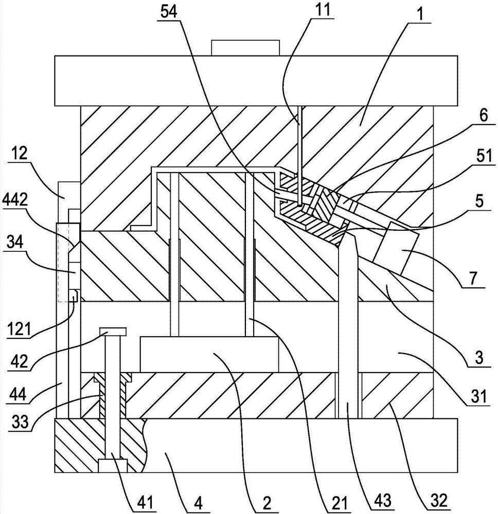
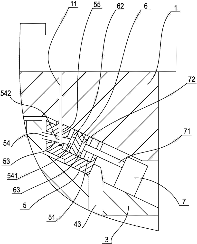
[0037] The injection molded part molding method of the present invention is suitable for products that simultaneously have side hole slots that require side core pulling in a side shape that requires side core pulling, and the core pulling direction of the side shape and the pulling direction of the side hole slots The core direction is inconsistent, that is, the large slider used to form the lateral shape and the core or small slider used to form the lateral hole slot need to be cored in different directions, and the lateral hole needs to be formed first. The core of the groove or the small slider is separated from the product before the large slider is cored, so as to avoid contact with the core or small slider still remaining in the side hole groove of the product when the large slider is cored. Blocks interfere with each other.

[0038] Su...


PUM


Abstract

The invention discloses an injection-molded part forming method requiring two stages of core pulling. During mold splitting, a core pulling oil cylinder drives a primary core pulling sliding block slidingly connected with the interior of a secondary core pulling sliding block to slide backwards, and the primary core pulling sliding block then drives a core pulling spindle slidingly connected with the primary core pulling sliding block to move backwards, so that primary core pulling is completed; the core pulling oil cylinder continues to act to pull the secondary core pulling sliding block to move backwards through the primary core pulling sliding block, so that secondary core pulling is completed; then, a product is ejected out of a movable mold; the core pulling oil cylinder acts backwards to allow the primary core pulling sliding block to move forwards, then to drive the core pulling spindle to move forwards and to stretch out of the forming end of the secondary core pulling sliding block; the core pulling oil cylinder continues to act to drive the secondary core pulling sliding block and the core pulling spindle to synchronously move forwards to reset, by this time, injection molding of a next product can begin. With the adoption method, a mould structure can be simplified, lateral core pulling in two any directions on one side of a product can be adapted, and backward movement of the core pulling spindle and the sliding blocks can be avoided.

Description

technical field [0001] The invention relates to an injection mold, in particular to a molding method of an injection molded part requiring secondary core pulling. Background technique [0002] Plastic products are very common in production and daily life, among which injection molding is the most common plastic product molding method, which usually includes a fixed mold on the upper side of the parting surface, a movable mold on the lower side of the parting surface, and a top plate, etc. , wherein the fixed mold is provided with a sprue sleeve, and the fixed mold and the movable mold are respectively provided with molding parts corresponding to the upper surface and the lower surface of the product. In order to make the molded product stay on the side of the movable mold, usually the molding part on the fixed mold is a cavity corresponding to the shape of the product, while the molding part on the movable mold is a core corresponding to the inner cavity of the product. The...

Claims


Application Information

Patent Timeline
Patent Type & Authority Applications(China)
IPC IPC(8): B29C45/33
CPCB29C45/332
Inventor 方立锋蔡炳芳项勇毛元源
Owner SHENTONG TECH GRP CO LTD
Why Eureka
Try Eureka