Multi-pose stop control hinge lock and door provided with same

A chain lock and pose technology, applied in door/window accessories, buildings, wing parts, etc., can solve the problems of kicking to the end of the strut, being dangerous, blocking, etc., to achieve clean space, avoid stumbling injuries, The effect of improving safety

Active Publication Date: 2018-11-30
江苏金迪木业股份有限公司
View PDF6 Cites 3 Cited by
  • Summary
  • Abstract
  • Description
  • Claims
  • Application Information

AI Technical Summary

Problems solved by technology

[0002] Household doors are usually of the rotary type. When the door is to be kept open, it must be closed to prevent it from being blown by the wind. When the door is fully open, the contacts on the door are magnetically constrained connected to the pole on the wall, and the door can be fixed; the problem with this technical solution is that due to the extension of the end of the pole on the wall Outside, when the human body passes by, if you do not pay attention, the ankle or instep will be kicked to the end of the pole, especially when there are underage children or young children in the family, this setting is more dangerous;
[0003] The layout of the family room cannot be completely rationalized because of the influence of the total area. In actual residential use, unreasonable door orientation or door position design will bring long-term distress to the occupants. One of the situations is as follows: figure 1 As shown, the bedroom door A1 and the bathroom door A2 are adjacent to the corner and arranged vertically. When the room needs to be ventilated, once the bedroom door is opened, the bathroom door will be blocked. This situation is very common in many small-sized houses Yes, in this case, the traditional method of locking a door by setting a pole on the wall cannot solve the problem;

Method used


Image

  • Multi-pose stop control hinge lock and door provided with same
  • Multi-pose stop control hinge lock and door provided with same
  • Multi-pose stop control hinge lock and door provided with same

Examples


Embodiment Construction

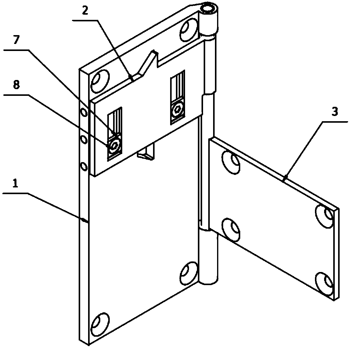
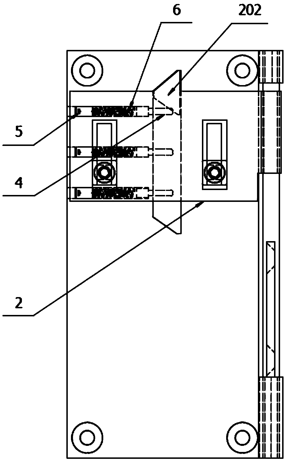
[0028] refer to Figure 2 to Figure 5 , Figure 8 ~ Figure 11, a hinge lock of the present invention, comprising a hinged fixed piece and a moving piece, the fixed piece 1 includes a fixed plate body 101, and one side of the fixed plate body 101 is respectively provided with an upper pin hole 103 and a lower pin hole 102, the moving piece 3 includes a moving plate body 301, one side of the moving plate body 301 is provided with a pin shaft 302, and the upper end and the lower end of the pin shaft 302 are rotatably inserted into the upper pin hole 103 and the upper pin hole 103 respectively. In the lower pin hole 102, during actual manufacture, the upper pin hole 103 and the lower pin hole 102 are crimped and formed by an edge folding machine after the pin shaft 302 is arranged in advance, and the upper end of the upper pin hole 103 will also be welded and sealed, so as to The pin shaft 302 realizes the axial restraint, and it is characterized in that: the multi-position parki...


PUM


Abstract

The invention discloses a hinge lock. The hinge lock comprises a fixed piece and a moving piece which are hinged to each other, and further comprises a sliding plate, ejection rods, a spring and a guiding sliding block; one side of the sliding plate is provided with a rod sleeve; the rod sleeve is internally provided with a thread A; a thread B d is arranged on a pin shaft of the moving piece; therod sleeve is arranged on the pin shaft of the moving piece in a sleeving mode; the rod sleeve and the pin shaft are in threaded connection through cooperation of the thread A and the thread B; the sliding plate is further provided with at least one chute; the other side, opposite to an upper pin hole and/or a lower pin hole, of the fixed piece is provided with a plurality of horizontally formedcountersunk pre-tightening holes; the inner ends of the countersunk pre-tightening holes communicate with a limiting groove; the ejection rods are inserted and connected into the countersunk pre-tightening holes; and the front ends of the ejection rods can extend out of the bottoms of the countersunk pre-tightening holes and extend into the limiting groove. A door can be locked through a speciallydesigned hinge when being opened, a support rod does not need to be arranged on a wall additionally, the indoor space is tidier, and the safety of the indoor space is improved.

Description

【Technical field】 [0001] The invention relates to the technical field of doors, in particular to a multi-posture parking control hinge lock and a door with the same. 【Background technique】 [0002] Household doors are usually of the rotary type. When the door is to be kept open, it must be closed to prevent it from being blown by the wind. When the door is fully open, the contacts on the door are magnetically constrained connected to the pole on the wall, and the door can be fixed; the problem with this technical solution is that due to the extension of the end of the pole on the wall Outside, when the human body passes by, if you do not pay attention, the ankle or instep will be kicked to the end of the pole, especially when there are underage children or young children in the family, this setting is more dangerous; [0003] The layout of the family room cannot be completely rationalized because of the influence of the total area. In actual residential use, unreasonable do...

Claims


Application Information

Patent Timeline
Patent Type & Authority Applications(China)
IPC IPC(8): E05D11/10
CPCE05D11/1028E05Y2900/132
Inventor 王玲娟王永虎
Owner 江苏金迪木业股份有限公司
Why Eureka
Try Eureka