Multi-target detection and positioning method based on constant false alarm rate detection
A positioning method and a technology of constant false alarm rate, applied in the field of life detection radar system, can solve the problems of inconstant false alarm rate, inaccurate estimation of background noise, increase the number of false targets, etc., and achieve the effect of avoiding the appearance of false targets
Pending Publication Date: 2018-11-30
INST OF ELECTRONICS CHINESE ACAD OF SCI
View PDF4 Cites 19 Cited by
- Summary
- Abstract
- Description
- Claims
- Application Information
AI Technical Summary
Problems solved by technology
The target is detected based on the same threshold value, which will lead to an unstable false alarm rate on the entire detection plane and increase the number of false targets
In addition, on the entire detection p
Method used
View moreImage
Smart ImageViewing Examples
Examples
 PUM
 Abstract
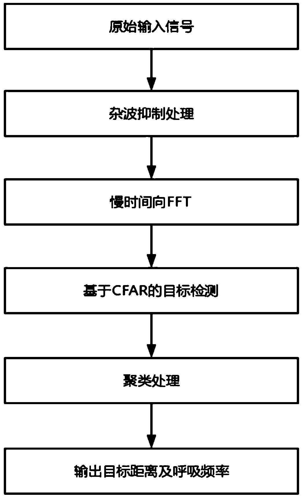
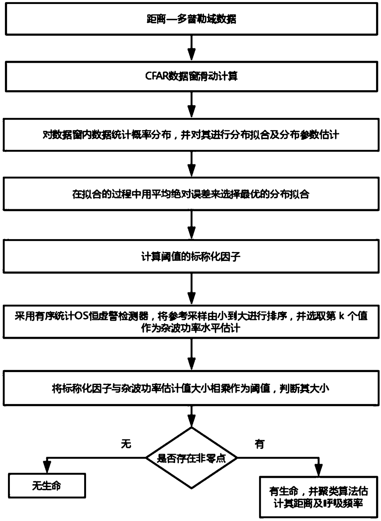
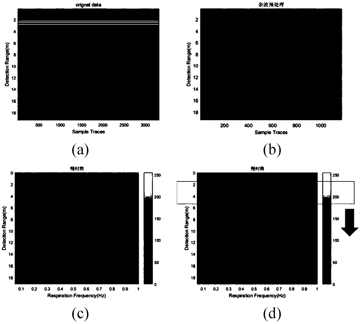
The invention provides a multi-target detection and positioning method for a life detecting radar based on constant false alarm rate detection, comprising the following steps: step A: inputting original signals, and arranging the original signals into B-SCAN maps according to the number of tracks, wherein a fast time direction includes distance information, and a slow time direction includes frequency information; step B: removing static clutters and linear trend items in the original data; step C: performing Fourier transform on all track information obtained at the same sampling time to obtain a distance-Doppler information map; step D: applying a CFAR-based target detection algorithm in a distance-Doppler domain, marking the target body on the distance-Doppler domain; and step E: determining whether there is a non-zero point in the image output by the CFAR, and performing target identification on the output result if there is a non-zero point, wherein the position information and the respiratory frequency of the output target are the same. The invention reduces false targets that occur due to interference from local strong noise.
Description
technical field [0001] The present invention relates to the technical field of life detection radar systems, in particular to a target detection and positioning method for life detection radar. Background technique [0002] In today's post-disaster rescue process, life detection radar has played a very important role, providing first-hand information for rescuers to determine whether there is life under the rubble. The life detection radar uses the principle that the radar echo reflected by the human body is periodic due to the fretting caused by human respiration and heartbeat. After removing the direct clutter, the life fretting signal can be detected in the frequency domain. In the application of life detection radar, the target detection algorithm is obviously an extremely important link, because the accuracy and efficiency of the detection algorithm largely determine the quality and effectiveness of the system results. Detecting targets based on the same threshold valu...
Claims
Login to View More Application Information
Patent Timeline
 IPC IPC(8): G01S13/04G01S13/06G01S7/41G01S13/88A61B5/08
CPCA61B5/0816G01S7/41G01S13/04G01S13/06G01S13/887
Inventor 叶盛波陈忠诚吴世有刘新吕晓华
Owner INST OF ELECTRONICS CHINESE ACAD OF SCI
Features
- R&D
- Intellectual Property
- Life Sciences
- Materials
- Tech Scout
- Unparalleled Data Quality
- Higher Quality Content
- 60% Fewer Hallucinations
Learn More Browse by: Latest US Patents, China's latest patents, Technical Efficacy Thesaurus, Application Domain, Technology Topic, Popular Technical Reports.
© 2025 PatSnap. All rights reserved.Legal|Privacy policy|Modern Slavery Act Transparency Statement|Sitemap|About US| Contact US: help@patsnap.com


