A kind of multi-level boost device

A multi-level, power supply technology, applied in output power conversion devices, electrical components, regulating electrical variables, etc., can solve the problem of overvoltage breakdown of the switch tube at the moment of power-on, and achieve the effect of avoiding breakdown failure.

Active Publication Date: 2020-03-24
SUNGROW POWER SUPPLY CO LTD
View PDF3 Cites 0 Cited by
  • Summary
  • Abstract
  • Description
  • Claims
  • Application Information

AI Technical Summary

Problems solved by technology

[0004] The invention provides a multi-level BOOST device to solve the problem of overvoltage breakdown of the switching tube at the moment of power-on in the prior art when the input voltage is relatively high

Method used


Image

  • A kind of multi-level boost device
  • A kind of multi-level boost device
  • A kind of multi-level boost device

Examples


Embodiment Construction

[0052] The following will clearly and completely describe the technical solutions in the embodiments of the application with reference to the drawings in the embodiments of the application. Apparently, the described embodiments are only some of the embodiments of the application, not all of them. Based on the embodiments in this application, all other embodiments obtained by persons of ordinary skill in the art without creative efforts fall within the protection scope of this application.

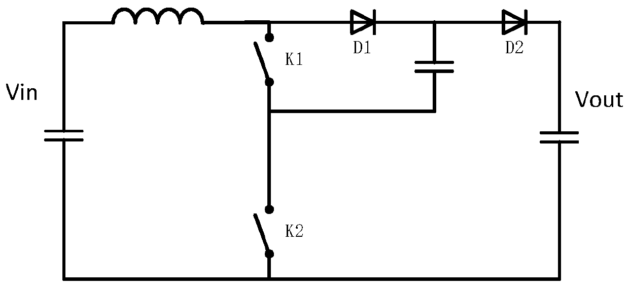
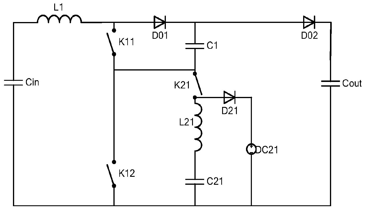
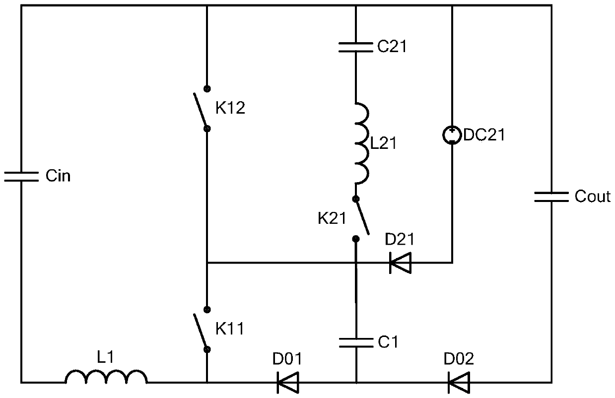
[0053] The invention provides a multi-level BOOST device to solve the problem in the prior art that there is a risk of device overvoltage breakdown at the moment of power-on when the input voltage is low.

[0054] In practical applications, a multi-level BOOST device generally includes a main circuit, a voltage and current detection device, and a controller; specifically, the main circuit can be as follows: Figure 2a , Figure 2b or Figure 2c As shown, including: input capacitor Cin, in...


PUM


Abstract

The present invention provides a multi-level BOOST device. By setting N voltage divider modules connected in series in series with N first switches in parallel one by one, voltage distribution between N first switches can be realized, and N The voltage at both ends of the first switch is within the safe range. Even if the input voltage is high and the voltage on the flying capacitor is zero when starting up, it can also avoid the failure of the second to Nth first switches due to overvoltage breakdown. question.

Description

technical field [0001] The invention relates to the technical field of power electronics, in particular to a multi-level BOOST device. Background technique [0002] With the rise of power electronic converter system voltage, the withstand voltage requirements for related switching devices are also gradually increasing. In view of the impact of semiconductor process performance and other aspects, multi-level technology can be realized at a lower cost by using lower voltage level devices. The power change of high voltage has become a research hotspot. [0003] figure 1 The main circuit topology of a common flying capacitor type three-level BOOST device is shown. Under normal circumstances, the voltage stress of K1, K2, D1 and D2 is half of the output voltage Vout. However, when the circuit is started, the voltage Vc across the capacitor C1 is 0V. If the input voltage Vin is higher than the withstand voltage of K2, K2 will break down due to overvoltage at the moment of power-...

Claims


Application Information

Patent Timeline
Patent Type & Authority Patents(China)
IPC IPC(8): H02M1/32H02M3/158
CPCH02M1/32H02M3/158H02M1/36H02M3/07H02M3/1584H02M1/0095H02M1/322H02M1/346H02M7/4837Y02B70/10
Inventor 庄加才徐君张兵王鹏文鹏
Owner SUNGROW POWER SUPPLY CO LTD
Why Eureka
Try Eureka