Supercharge Your Innovation With Domain-Expert AI Agents!

Elastic hook heat sink structure

A heat sink and hook type technology, applied in the field of the hook type heat sink structure, can solve the problems of affecting the heat dissipation effect, the deflection of the heat sink, the inability of the chip and the heat sink to fit, etc., and achieve the effect of improving the assembly deflection.

Inactive Publication Date: 2020-09-29
NANNING FUGUI PRECISION IND CO LTD
View PDF6 Cites 0 Cited by
  • Summary
  • Abstract
  • Description
  • Claims
  • Application Information

AI Technical Summary

Problems solved by technology

[0003] After the existing snap-hook heat sink is assembled, due to the symmetry of the snap-hook process, the force on the heat sink is not only the original vertical compression force, but also the tension in the X-Y direction, which in turn causes the heat sink to be fixed. Afterwards, there will be a deflection situation, so that the chip and the heat sink cannot be bonded in the correct position, which will affect the heat dissipation effect

Method used


Image

  • Elastic hook heat sink structure
  • Elastic hook heat sink structure
  • Elastic hook heat sink structure

Examples


Embodiment Construction

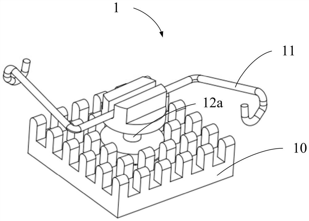
[0041] refer to figure 1 , figure 1 It is a schematic diagram of the snap-hook heat sink structure 1 of the embodiment of the present invention. The spring-hook heat sink structure 1 includes a heat sink 10 , a spring hook 11 and a rotating shaft 12 a. One end of the rotating shaft 12 a is connected to the heat sink 10 , and the other end is connected to the spring hook 11 , and the spring hook 11 can rotate along the rotating shaft 12 . That is to say, in this embodiment, the rotating shaft 12a can rotate, and the rotating shaft 12 will not drive the heat sink 10 connected thereto to rotate.

[0042] The spring-hook type heat sink structure 1 provided in the embodiment of the present invention replaces the existing method of directly riveting the spring hook 11 to the body of the heat sink 10 by connecting the rotating shaft 12 a to the spring hook 11 . Since the spring hook 11 is connected to the rotatable shaft 12a, the body of the heat sink 10 will only be subjected to ...


PUM


Abstract

A spring hook type cooling fin structure comprises a cooling fin, a spring hook and a rotation shaft. One end of the rotation shaft is connected to the cooling fin and the other end is connected to the spring hook. The spring hook can rotate along the rotation shaft. By using the spring hook type cooling fin structure, after the spring hook is assembled with the spring hook in a PCB, even if thereis horizontal tension, a cooling fin body is not affected, and the cooling fin can still maintain an original fixed position so as to improve the deflection condition of traditional spring hook typecooling fin assembling.

Description

technical field [0001] The invention relates to heat sinks, in particular to a snap-hook type heat sink structure. Background technique [0002] At present, the common spring-hook heat sink on the market is composed of a metal spring hook and the body of the heat sink riveted together. When the heat sink is assembled, the hooks at both ends of the spring hook are fastened and fixed with the corresponding spring hooks on the PCB. [0003] After the existing snap-hook heat sink is assembled, due to the symmetry of the snap-hook process, the force on the heat sink is not only the original vertical compression force, but also the tension in the X-Y direction, which leads to the heat sink being fixed. Afterwards, there will be a deflection situation, so that the chip and the heat sink cannot be bonded in the correct position, which will affect the heat dissipation effect. Contents of the invention [0004] In view of this, it is necessary to provide a spring-hook type heat sin...

Claims


Application Information

Patent Timeline
Patent Type & Authority Patents(China)
IPC IPC(8): H05K7/20
CPCH05K7/2039
Inventor 黄志扬
Owner NANNING FUGUI PRECISION IND CO LTD
Features
  • R&D
  • Intellectual Property
  • Life Sciences
  • Materials
  • Tech Scout
  • Unparalleled Data Quality
  • Higher Quality Content
  • 60% Fewer Hallucinations
Learn More