Computer equipment maintenance box

A technology for equipment maintenance and maintenance box, which is applied in the direction of removing smoke and dust, dispersing particle filtration, cleaning methods and appliances, etc. various effects

Inactive Publication Date: 2018-12-07
合肥锦和信息技术有限公司
View PDF0 Cites 5 Cited by
  • Summary
  • Abstract
  • Description
  • Claims
  • Application Information

AI Technical Summary

Problems solved by technology

The traditional computer equipment maintenance box can only simply provide people with the function of computer equipment maintenance, which is convenient for people to maintain and repair computer equipment. The function is relatively single and cannot meet people's needs.
At the same time, when the co

Method used


Image

  • Computer equipment maintenance box
  • Computer equipment maintenance box
  • Computer equipment maintenance box

Examples


Embodiment 1

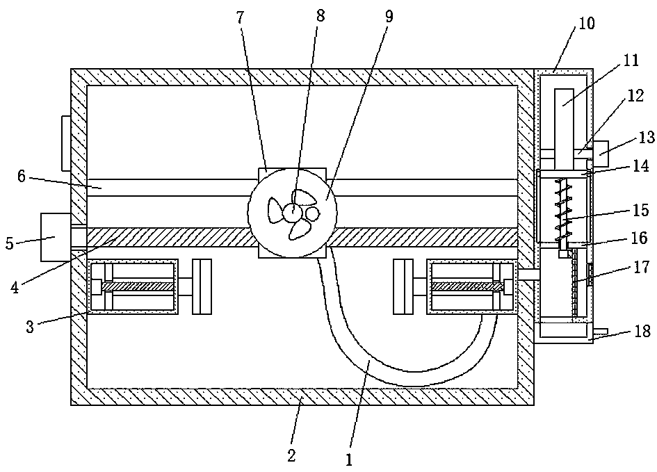
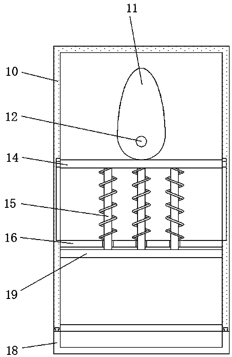
[0021] Embodiment 1: When the computer equipment needs to be maintained, put the computer equipment into the maintenance box 2, and make the side of the computer equipment close to the air vent be located inside the maintenance box 2, close the box door 20, and the DATA-7311 controller controls The first motor 5 and the blower 8 work, and the first motor 5 drives the first leading screw 4 to start rotating. Since the movable seat 7 is threadedly connected with the first leading screw 4, the movable seat 7 is slidably connected on the slide bar 6 and cannot rotate. , so that the movable seat 7 can move back and forth inside the maintenance box 2, so that the exhaust fan 8 vacuums the computer equipment back and forth, and the dust inside the computer equipment is separated from the computer equipment under the action of the exhaust fan 8, and passes through the vent Enter the dust collection hood 9, and then enter the dust collection box 10 through the dust suction pipe 1, the a...

Embodiment 2

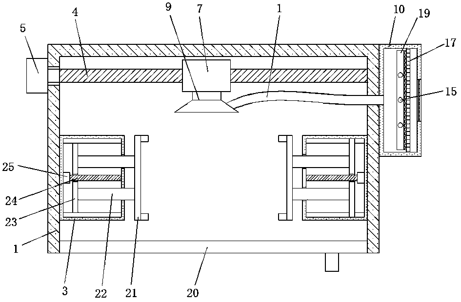
[0022]Embodiment 2: When the computer equipment needs to be maintained, open the back shell of the computer equipment to facilitate the dust removal of the computer equipment, put the computer equipment into the maintenance box 2, and make the side of the computer equipment close to the back shell be located in the maintenance box 2 close the box door 20, the DATA-7311 controller controls the first motor 5 and the exhaust fan 8 to work, and the first motor 5 drives the first lead screw 4 to start rotating. Since the movable seat 7 is threadedly connected with the first lead screw 4, Simultaneously, movable seat 7 is slidably connected on slide bar 6 and cannot rotate, so that movable seat 7 can move back and forth in the inside of maintenance box 2, thereby making exhaust fan 8 carry out dust suction back and forth to computer equipment, and the dust inside computer equipment is in exhaust fan 8 is separated from the computer equipment, and enters the dust box 10 through the du...


PUM


Abstract

The invention discloses a computer equipment maintenance box which comprises a maintenance box body. A box door is arranged on one side of the maintenance box body. A first motor is fixed to the middle position of the outer wall of the side, away from the box door, of the maintenance box body. An output shaft of the first motor is connected with a first lead screw. One end of the first lead screwpenetrates through the outer wall of the maintenance box body to be rotationally connected to the inner wall of the maintenance box body. A moving seat is in threaded connection to the first lead screw. A dust suction cover is arranged on the side wall of the side, close to the box door, of the moving seat. An exhaust fan is arranged in the dust suction cover. The maintenance box can have the maintenance function, effective dust removal can be carried out on computer equipment according to needs, and functions are diversified; dust is sucked out of the maintenance box in an air draft manner, the situation that normal work of the computer equipment is influenced by too much dust is avoided, and the dust removal effect is good; and when repaired and maintained, the computer equipment can beeffectively fixed, and the situation that the computer equipment moves, and consequently normal repair and maintenance of the computer equipment are influenced is avoided.

Description

technical field [0001] The invention relates to the technical field of computer equipment, in particular to a maintenance box for computer equipment. Background technique [0002] With the development of science and technology, computer equipment has gradually entered thousands of households, bringing great convenience to people's work and life. With the popularity of computer equipment, the post-maintenance of computer equipment has also received more and more attention. The traditional computer equipment maintenance box can only simply provide the function of computer equipment maintenance for people to facilitate people to carry out maintenance and repair work on computer equipment. The function is relatively single and cannot meet people's needs. At the same time, when the computer equipment is maintained and repaired, the computer equipment is not fixed well, so the computer equipment is easy to move during operation, which affects the maintenance and repair work, and ...

Claims


Application Information

Patent Timeline
IPC IPC(8): B08B5/04B08B15/04B08B13/00B01D46/00B01D46/10
CPCB01D46/10B08B5/04B08B13/00B08B15/04B01D46/681
Inventor 不公告发明人
Owner 合肥锦和信息技术有限公司
Why Eureka
Try Eureka