Self-centering chuck device

A self-centering chuck and chuck technology, applied in the direction of the chuck, etc., can solve the problems of affecting the verification accuracy, the flowmeter cannot be verified, and easy to dislocate, etc., to achieve the effect of simple operation, improved verification efficiency, and simplified installation and operation.

Pending Publication Date: 2018-12-07
WUHAN INST OF MEASUREMENT & TESTING TECH
View PDF7 Cites 6 Cited by
  • Summary
  • Abstract
  • Description
  • Claims
  • Application Information

AI Technical Summary

Problems solved by technology

[0002] Existing flow standard device pipelines generally use flange joints. If the clamping of DN10-DN40 caliber flowmeters connected by threads or chucks is not concentric, it is easy to be misaligned during docking, which does not comply with JJG1029-2007 "Vortex Flowmeter Verification Regulations" "And JJG1033-2007 "Electromagnetic Flowmeter Verification Regulations" in clause 7.1.4.3 requires that "during installation, ensure that the flowmeter measurement pipeline is in the same direction as the pipeline axis", clause 7.1.4.4 requires that "the connection between the flowmeter and the pipeline should have no leakage , the gasket at the joint cannot protrude into the pipeline", JJG1037-2008 "Verification Regulations for Turbine Flowmeters" and JJG1038-2008 "Verification Regulations for Mass Flowmeters" require that "the flowmeter and the front and rear straight pipe sections should be coaxial Installation, the connection part of the test pipe section should have no leakage, and the gasket at the connection point should not protrude into the fluid pipeline" and other requirements, which will produce complex flow phenomena such as unstable vortex and secondary flow and affect the verification accuracy.
Due to the inconsistency of the flowmeter joints and the incomplete accessories in the clamping process, many flowmeters cannot be calibrated because they cannot be clamped.

Method used


Image

  • Self-centering chuck device
  • Self-centering chuck device
  • Self-centering chuck device

Examples


Embodiment Construction

[0016] The present invention will be further described in detail below in conjunction with the accompanying drawings and specific embodiments.

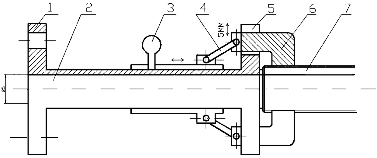
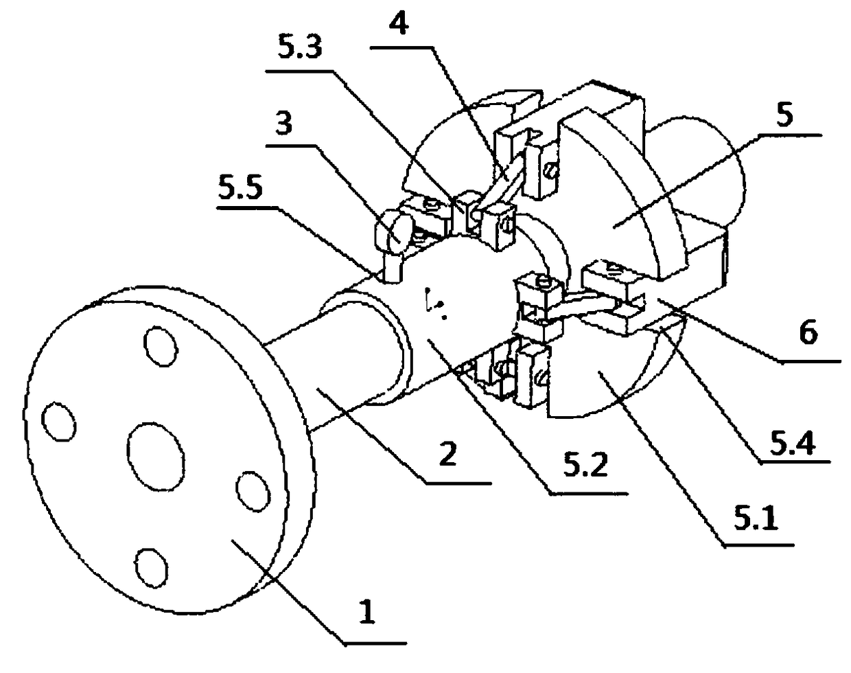
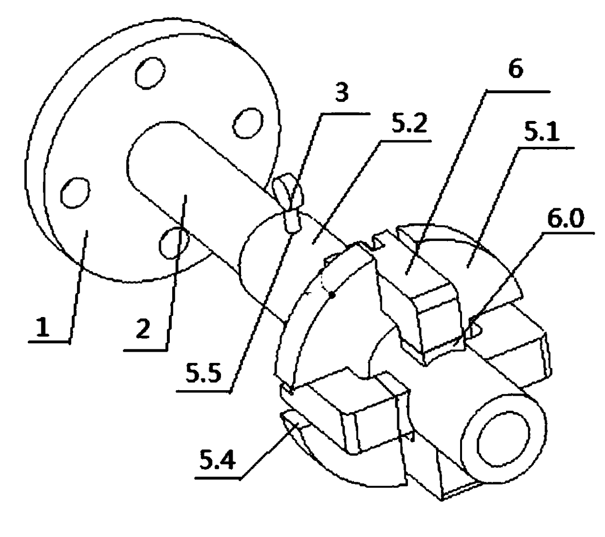
[0017] The self-centering chuck device as shown in the figure includes a pipe flange 1 provided with a standard straight pipe section 2, a chuck assembly sleeved on the pipe flange 1, and the chuck assembly includes a positioning screw 3, a chuck Disk body 5, movable claw 6; chuck body 5 is composed of chuck 5.1 and sleeve 5.2, one end of sleeve 5.2 is sleeved outside the standard straight pipe section 2, the other end of sleeve 5.2 is connected with chuck 5.1, sleeve The outer wall of the cylinder 5.2 is provided with a boss 5.3; it is also provided with a claw drive rod 4, and the two ends of the claw drive rod 4 are respectively hinged with the boss 5.3 and the movable claw 6; The slot 5.4 of 6; the sleeve 5.2 is provided with a positioning hole 5.5, and the positioning screw 3 is connected with the positioning hole 5.5.

[0018] ...


PUM


Abstract

The invention discloses a self-centering chuck device. The self-centering chuck device comprises a pipeline flange plate provided with a standard straight pipe section and a chuck assembly which sleeves the pipeline flange pipeline, wherein the chuck assembly comprises a positioning screw rod, a chuck body and a movable clamping claw, wherein the chuck body is composed of a chuck and a sleeve; oneend of the sleeve sleeves the standard straight pipe section, the other end of the sleeve is connected with the chuck, and a boss is arranged on the outer wall of the sleeve; a clamping claw drivingrod is further arranged, and the two ends of the clamping claw driving rod are hinged to the boss and the movable clamping claw correspondingly; and a clamping groove used for containing the movable clamping jaw is formed in the chuck; a positioning hole is formed in the sleeve, and the positioning screw rod is connected with the positioning hole. According to the device, a portable design is adopted, the operation is simple and reliable, and the installation precision and the meter clamping efficiency of a flowmeter can be effectively improved, so that clamping requirements of various non-flange type flow meters can be met.

Description

technical field [0001] The invention relates to the field of instrument measurement, in particular to a self-centering chuck device. Background technique [0002] Existing flow standard device pipelines generally use flange joints. If the clamping of DN10-DN40 caliber flowmeters connected by threads or chucks is not concentric, it is easy to be misaligned during docking, which does not comply with JJG1029-2007 "Vortex Flowmeter Verification Regulations" "And JJG1033-2007 "Electromagnetic Flowmeter Verification Regulations" in clause 7.1.4.3 requires that "during installation, ensure that the flowmeter measurement pipeline is in the same direction as the pipeline axis", clause 7.1.4.4 requires that "the connection between the flowmeter and the pipeline should have no leakage , the gasket at the joint cannot protrude into the pipeline", JJG1037-2008 "Verification Regulations for Turbine Flowmeters" and JJG1038-2008 "Verification Regulations for Mass Flowmeters" require that "t...

Claims


Application Information

Patent Timeline
Patent Type & Authority Applications(China)
IPC IPC(8): B23B31/117
CPCB23B31/117
Inventor 许建平洪传文熊皓刘伟郭均瑶
Owner WUHAN INST OF MEASUREMENT & TESTING TECH
Why Eureka
Try Eureka