Novel high-strength anchorage device

A high-strength, anchorage technology, which is applied in the direction of building reinforcements, bridge parts, structural elements, etc., can solve the problems of wire cutting damage to steel wire cutting, uneven force on the wire splitting board, and reduced anchorage bearing capacity. Achieve the effects of being conducive to axial force bearing, easy to popularize, and improving strength and service life

Inactive Publication Date: 2018-12-07
马鞍山平文锻造有限公司
View PDF0 Cites 5 Cited by
  • Summary
  • Abstract
  • Description
  • Claims
  • Application Information

AI Technical Summary

Problems solved by technology

[0002] Prestressed anchors are widely used in bridges, buildings and other fields. However, the steel wire holes on the wire splitter plates commonly used at present are all perpendicular to the surface of the splitter wire boards, which makes the splitter boards cause cutting damage to the steel wires and reduces the anchorage. The load-bearing capacity of the tool, and most of the splitter boards are flat structures, so that the stress on the splitter board is uneven, and the force on the central part is the largest. When used under heavy loads, cracks are prone to damage, and the anchor cups of the current anchorage are all With the same taper, the radial component force is large, which is easy to cause radial deformation of the anchor cup. Therefore, it is necessary to design a high-strength prestressed anchor.

Method used


Image

  • Novel high-strength anchorage device
  • Novel high-strength anchorage device
  • Novel high-strength anchorage device

Examples


Embodiment Construction

[0013] The present invention will be described in further detail below in conjunction with the accompanying drawings.

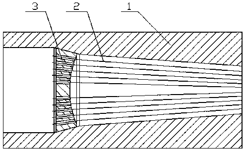
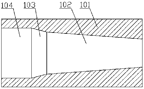
[0014] Such as figure 1 It is a structural schematic diagram of the present invention, a new type of high-strength anchorage, including anchor cup (1), prestressed steel wire (2), and splitter plate (3), characterized in that the splitter plate (3) is placed in the anchor cup Inside (1), the prestressed steel wire (2) passes through the anchor cup (1) and the splitter plate (3), and is fixed on the end face of the splitter plate (3). The anchor cup (1) includes an anchor cup body (101), a first tapered hole (102), a second tapered hole (103), and a through hole (104). The inner hole is divided into three parts, namely the first tapered hole (102), the second taper hole (103), the through hole (104), the taper of the first taper hole (102) is 0.1~0.2, the taper of the second taper hole (103) is 0.2~0.3, the second taper hole Using a taper larger than the fir...


PUM


Abstract

The invention provides a novel high-strength anchorage device which comprises an anchorage cup, prestressed steel wires and a wire separation board. The novel high-strength anchorage device is characterized in that the wire separation board is arranged in the anchorage cup, and the prestressed steel wires penetrate through the anchorage cup and the wire separation board and are fixed to the end face of the wire separation board. The taper of a first taper hole of the anchorage cup is between 0.1 and 0.2, the taper of a second taper hole is between 0.2 and 0.3, the second taper hole adopts thetaper larger than that of the first taper hole, more stress of the wire separation board is converted into axial stress, axial force bearing is further facilitated, the stress stability of the anchorage device is improved, and deformation of the anchorage cup is reduced. The taper of the outer surface of a wire separation board body is identical to that of the large taper hole of the anchorage cup, the ratio of the radius of curvature of a groove to the radius of the wire separation board body is 1:1, the stress on the wire separation board is even, steel wire holes point at the peak of the first taper hole of the anchorage cup, and shearing damage of the wire separation board to the steel wires is reduced. The strength of the anchorage device is improved, the service life of the anchoragedevice is prolonged, practicability is high, popularization is easy, and economic benefits are good.

Description

technical field [0001] The invention relates to a prestressed anchor, in particular to a novel high-strength anchor. Background technique [0002] Prestressed anchors are widely used in bridges, buildings and other fields. However, the steel wire holes on the commonly used anchorage wire splitter boards are all perpendicular to the surface of the splitter wire boards, so that the wire splitters cause cutting damage to the steel wires and reduce the anchorage. The load-bearing capacity of the tool, and most of the splitter boards are flat structures, so that the stress on the splitter board is uneven, and the force on the central part is the largest. When used under heavy loads, cracks are prone to damage, and the anchor cups of the current anchorage are all If the same taper is used, the radial component force will be larger, which will easily cause the radial deformation of the anchor cup. Therefore, it is necessary to design a high-strength prestressed anchor. Contents o...

Claims


Application Information

Patent Timeline
Patent Type & Authority Applications(China)
IPC IPC(8): E01D19/00E04C5/12
CPCE01D19/00E04C5/12
Inventor 胡平
Owner 马鞍山平文锻造有限公司
Why Eureka
Try Eureka