Formwork supporting structure of concrete cast-in-place construction

A formwork support and concrete technology, which is applied to the on-site preparation of building components, pillars, building structures, etc., can solve the problems of wood loss, troublesome formwork laying, poor forming quality of concrete walls, etc., and achieve the effect of strengthening the tensioning effect.

Inactive Publication Date: 2018-12-07
徽都建设有限公司
View PDF4 Cites 8 Cited by
  • Summary
  • Abstract
  • Description
  • Claims
  • Application Information

AI Technical Summary

Problems solved by technology

[0002] The formwork support used for cast-in-place concrete walls in construction projects generally adopts the combination of steel pipes and metal fasteners to connect wooden squares. The existing problems are that the assembly and construction workload is large, time-consuming and laborious, serious wood loss, and low construction efficiency. high cost
And the poor flatness of the formed formwork support surface brings troubles to the laying of the formwork, and at the same time leads to poor molding quality of the concrete wall
[0003] With various design requirements in the building construction process, the concrete formwork can be poured to meet the design requirements by increasing the height of the wall. The higher the building floor, the higher the height of the concrete pouring rise correspondingly, and the force that the formwork bears is in There are differences in the vertical direction. Therefore, the traditional method of supporting the formwork with only one support point can no longer meet the needs of high formwork. Therefore, a formwork support structure for concrete cast-in-place construction is urgently needed

Method used


Image

  • Formwork supporting structure of concrete cast-in-place construction
  • Formwork supporting structure of concrete cast-in-place construction
  • Formwork supporting structure of concrete cast-in-place construction

Examples


Embodiment Construction

[0019] The following will clearly and completely describe the technical solutions in the embodiments of the present invention with reference to the accompanying drawings in the embodiments of the present invention. Obviously, the described embodiments are only some, not all, embodiments of the present invention. Based on the embodiments of the present invention, all other embodiments obtained by persons of ordinary skill in the art without making creative efforts belong to the protection scope of the present invention.

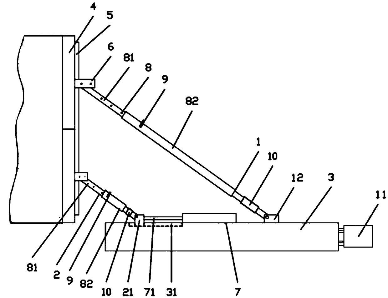
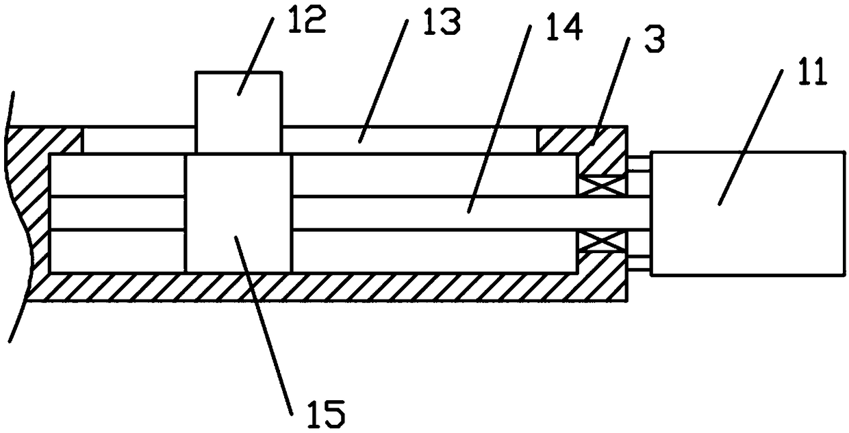
[0020] see Figure 1~3 , in an embodiment of the present invention, a formwork support structure for concrete cast-in-place construction, including a long support bar 1, a short support bar 2, and a base 3, wherein at least one of the lower ends of the long support bar 1 and the short support bar 2 is connected to the base 3 Sliding connection, the upper ends of the long support rod 1 and the short support rod 2 are provided with a connecting piece 6 for conne...


PUM


Abstract

The invention discloses a formwork supporting structure of concrete cast-in-place construction. The formwork supporting structure of the concrete cast-in-place construction comprises a long supportingrod, a short supporting rod and a base. The base is slidably connected to at least one lower end of the long supporting rod and the short supporting rod, connecting pieces used for connecting a longitudinal beam arranged on a formwork are arranged at the upper ends of the long supporting rod and the short supporting rod, at least one connecting piece is adjustably connected with the longitudinalbeam, the long supporting rod and the short supporting rod are telescopic structures, and the base is fixedly connected with the lower end of the long supporting rod through a fine adjustment piece. The lengths of the supporting rods are adjusted by adjusting pin clamping buckles in different adjusting holes, then the lower ends of the supporting rods are adjusted inwards and outwards in a movingmode, a sliding block arranged at the lower end of supporting rods is pushed by a push rod of a jack to move inwards in a sliding groove formed in the base to a proper position and is fixed, the tensioning effect of the supporting rods is further improved by adjusting the fine adjustment piece.

Description

technical field [0001] The invention relates to a formwork support structure, in particular to a formwork support structure for concrete cast-in-place construction. Background technique [0002] The formwork support used for cast-in-place concrete walls in construction projects generally adopts the combination of steel pipes and metal fasteners to connect wooden squares. The existing problems are that the assembly and construction workload is large, time-consuming and laborious, serious wood loss, and low construction efficiency. high cost. And the poor flatness of the formed formwork support surface brings troubles to the laying of the formwork, and causes poor molding quality of the concrete wall. [0003] With various design requirements in the building construction process, the concrete formwork can be poured to meet the design requirements by increasing the height of the wall. The higher the building floor, the higher the height of the concrete pouring rise correspondi...

Claims


Application Information

Patent Timeline
IPC IPC(8): E04G25/04
CPCE04G25/04
Inventor 吕宗霞江玲叶兴国吕俊杰
Owner 徽都建设有限公司
Why Eureka
Try Eureka