Passive electronic lock cylinder

An electronic lock and lock cylinder technology, applied in electric alarm locks, building locks, non-mechanical transmission-operated locks, etc., can solve the problems of increased cost, serious generalization of mechanical keys, low security of key management, etc., to save energy. Effect

Pending Publication Date: 2018-12-07
ZHONGTIAN BROADBAND TECH
View PDF0 Cites 1 Cited by
  • Summary
  • Abstract
  • Description
  • Claims
  • Application Information

AI Technical Summary

Problems solved by technology

[0002] A large number of passive cabinets and site computer rooms all use mechanical locks, and because different suppliers have also introduced a large number of different types of keys, it is impossible to manage effectively through manpower, let alone centralized control
The disadvantage of mechanical locks is the low security of key management: it is difficult to effectively guarantee the implementation of the mechanical key borrowing and return system, and the use of mechanical keys to switch locks cannot generate effective switch records, and problems cannot be traced or held accountable; the generalization of mechanical keys is serious and And it is easy to copy or buy, causing the lock to be useless, easy to misuse the line or other safety accidents
[0003] With

Method used


Image

  • Passive electronic lock cylinder
  • Passive electronic lock cylinder
  • Passive electronic lock cylinder

Examples


Embodiment Construction

[0023] The present invention will be further described in detail with reference to the accompanying drawings and embodiments. The following embodiments are for explaining the present invention and the present invention is not limited to the following embodiments.

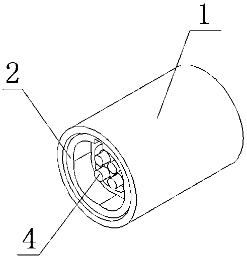
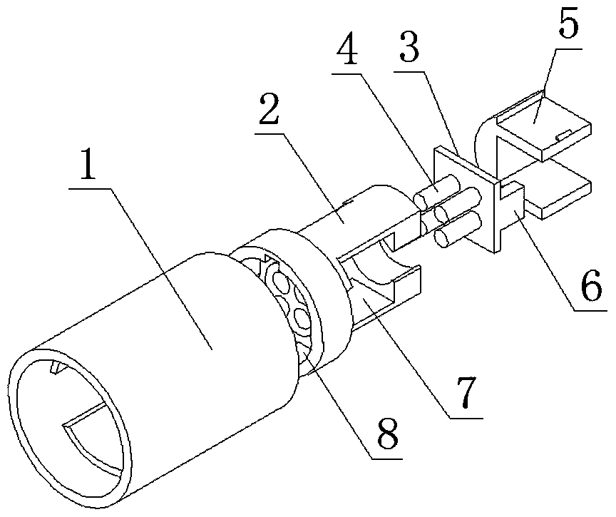
[0024] Such as figure 1 with figure 2 As shown, a passive electronic lock cylinder of the present invention includes a housing 1, a lock cylinder metal cover 2, a circuit board 3, a lock cylinder pin 4, a plastic locking groove 5 and a communication connector 6, and a lock cylinder metal cover 2 has a cavity 7 that matches the shape of the circuit board 3 on one side of the main body part. The communication connector 6 is perpendicular to the circuit board 3 and fixed on one side of the circuit board 3, and the lock cylinder pin 4 is perpendicularly fixed to the other of the circuit board 3. On the side, one end of the lock cylinder metal cover 2 protrudes outward and the end has a circular groove 8. The circular groov...


PUM


Abstract

The invention discloses a passive electronic lock cylinder. The passive electronic lock cylinder comprises a shell, a lock cylinder metal cover, a circuit board, lock cylinder pins, a plastic lockinggroove and a communication connecting piece. An accommodating cavity of which the shape is matched with the shape of the circuit board is formed in one side of the body part of the lock cylinder metalcover, and the communication connecting piece is perpendicular to the circuit board and fixed to one side of the circuit board. The lock cylinder pins are perpendicularly fixed to the other side of the circuit board, and the circuit board is inserted into the accommodating cavity from the side surface of the accommodating cavity and inserts the lock cylinder pins into through holes laterally along the through holes in the lock cylinder metal cover. Two U-shaped insertion arms of the plastic locking groove pass through slotted holes and the side surfaces of the insertion arms abut against oneside of the circuit board to fix the circuit board into the lock cylinder metal cover in a lock mode. The lock cylinder metal cover is inserted into the shell from one end of a step groove and is fixed to the inner wall of the shell in a distensible mode. The passive electronic lock cylinder can keep an electronic lock in a passive state when in a normal passive state, and the lock cylinder of theelectronic lock is subjected to temporary power supply and communication by an electronic key at any time when unlocking is required, so that unlocking is realized and energy is saved.

Description

Technical field [0001] The invention relates to an electronic lock cylinder, in particular to a passive electronic lock cylinder. Background technique [0002] A large number of passive cabinets and site computer rooms are all mechanical locks, and different types of massive keys have been introduced due to different suppliers, which cannot be effectively managed by manpower, let alone centralized control. The disadvantage of mechanical locks is the low security of key management: the mechanical key borrowing and returning system is difficult to effectively guarantee the implementation, the use of mechanical key switch locks cannot generate effective switch records, and problems cannot be traced or accountable; mechanical keys are universal It is very easy to copy or buy, resulting in the locks being useless, easy to line misoperation or other safety accidents. [0003] With the development of electronic technology, electronic technology has been widely used in the lock industry. ...

Claims


Application Information

Patent Timeline
IPC IPC(8): E05B47/00E05B45/06G07C9/00
CPCG07C9/00174E05B45/061E05B47/0012G07C2009/00753E05B2047/0063
Inventor 缪爱林郝亮李莉华缪冬青解勇汤俊勇
Owner ZHONGTIAN BROADBAND TECH
Why Eureka
Try Eureka