A fixed hoop for a composite material tower

A composite material and pole tower technology, which is applied in the direction of friction clamping detachable fasteners, connecting components, mechanical equipment, etc., can solve the problem that the hoop cannot realize the adjustment function of the contact area, threaten the safe operation of the transmission line, and the electrical safety distance Changes and other issues, to achieve the effect of improving the scope of use, improving safety, and improving firmness

Active Publication Date: 2020-09-01
HEFEI HAIYIN TOWER
View PDF5 Cites 0 Cited by
  • Summary
  • Abstract
  • Description
  • Claims
  • Application Information

AI Technical Summary

Problems solved by technology

[0002] The hoop is a common connecting part used to fix components such as towers, crossarms and tie rods. It is an indispensable fastener in power line engineering. However, in recent years, with the use of composite material towers and composite The advantages of application technology are gradually reflected. Composite material towers have become an ideal substitute for traditional tower products. If traditional hoop connections are used to connect and fix composite material components such as composite material In the case of installation or disconnection, the hoop is prone to relative displacement and deflection, which leads to changes in the electrical structure design, changes in the discharge gap, and a corresponding change in the electrical safety distance, which greatly threatens the safe operation of the transmission line, and many There is no slack warning function for the hoop during use, and even some hoops cannot realize the adjustment function of the contact area during use, which affects the safety of the hoop.

Method used


Image

  • A fixed hoop for a composite material tower
  • A fixed hoop for a composite material tower
  • A fixed hoop for a composite material tower

Examples


Embodiment Construction

[0014] The following will clearly and completely describe the technical solutions in the embodiments of the present invention with reference to the accompanying drawings in the embodiments of the present invention. Obviously, the described embodiments are only some, not all, embodiments of the present invention. Based on the embodiments of the present invention, all other embodiments obtained by persons of ordinary skill in the art without making creative efforts belong to the protection scope of the present invention.

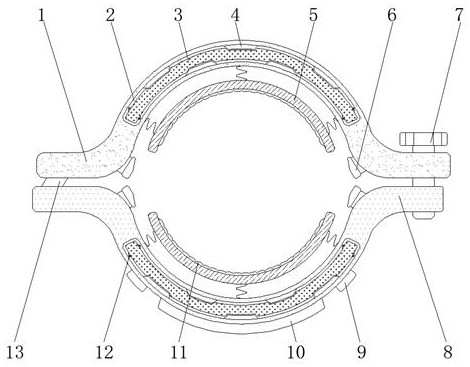
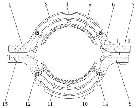
[0015] see Figure 1-3 , an embodiment provided by the present invention: a fixed hoop for a composite material tower, including a rear end hoop 1, a retractable chamber 2, an arc-shaped extension plate 3, a hinged support 13 and a rotating through cavity 15, and the rear end hoop A hinged strut 13 is installed on the inner wall of one end of the hoop 1, and the end of the rear hoop 1 away from the hinged strut 13 is threadedly connected with a locking screw 7...


PUM


Abstract

The invention discloses a fixing hoop for a composite material pole tower. The fixing hoop comprises a rear-end hoop, taking-up and paying-off cavities, arc-shaped stretching plates, a hinge joint support pillar and a rotating through cavity. The hinge joint support pillar is mounted on the inner side wall of one end of the rear-end hoop. A front-end hoop is arranged at one side of the rear-end hoop. The rotating through cavity is formed in the inner side wall, close to one end of the rear-end hoop, of the front-end hoop. Extrusion force sensors are fixed to the inner side walls of portions, at the two sides of the arc-shaped stretching plates, of the rear-end hoop and the front-end hoop correspondingly. The taking-up and paying-off cavities are formed in the centers of the top end of therear-end hoop and the top end of the front-end hoop correspondingly. Extending-and-contracting rods are fixed to the two ends inside the taking-up and paying-off cavities correspondingly. A treatmentcavity is fixed to the center of the outer side wall of the front-end hoop. A single chip microcomputer is mounted at one end inside the treatment cavity. By means of the fixing hoop, fixing firmnessof the hoop is improved, and the alarm function is achieved when the hoop is loosened; and in addition, the function of adjusting the contact area of the hoop and the pole tower is achieved.

Description

technical field [0001] The invention relates to the technical field of composite material towers, in particular to a fixed hoop for composite material towers. Background technique [0002] The hoop is a common connecting part used to fix components such as towers, crossarms and tie rods. It is an indispensable fastener in power line engineering. However, in recent years, with the use of composite material towers and composite The advantages of application technology are gradually reflected. Composite material towers have become an ideal substitute for traditional tower products. If traditional hoop connections are used to connect and fix composite material components such as composite material In the case of installation or disconnection, the hoop is prone to relative displacement and deflection, which leads to changes in the electrical structure design, changes in the discharge gap, and a corresponding change in the electrical safety distance, which greatly threatens the sa...

Claims


Application Information

Patent Timeline
Patent Type & Authority Patents(China)
IPC IPC(8): F16B2/06
CPCF16B2/065
Inventor 李光海赵宏伟
Owner HEFEI HAIYIN TOWER
Why Eureka
Try Eureka