Water injection backflow prevention end cover of water storage valve

A technology of preventing backflow and end cap, applied in valve details, valve device, valve shell structure, etc., can solve the problems of hidden danger, malfunction, economic loss and other problems of deluge alarm valve, and achieve the effect of avoiding a large amount of gushing

Inactive Publication Date: 2016-03-02
全爱军
View PDF0 Cites 0 Cited by
  • Summary
  • Abstract
  • Description
  • Claims
  • Application Information

AI Technical Summary

Problems solved by technology

[0002] Now many places have installed deluge alarm valves. The current deluge alarm valves have the following problems. After the water supply system is overhauled and the water is cut off, the deluge alarm valve must be re-operated on site to make it stand up again. In metallurgy, electric power Large-scale protection areas such as chemical industry, traffic tunnels, and papermaking, and places where fire water sources are shared, maintenance is troublesome, and misoperations often occur, causing undue economic losses
Moreover, the deluge alarm valve in some places has not been used for a long time, and even the deluge alarm valve in some places has not been used since it was installed at the beginning. Such a deluge alarm valve has certain hidden safety hazards. When it comes, can the deluge alarm valve respond quickly and make water to put out the fire? In order to solve the above problems, we need to overhaul the deluge alarm valve at corresponding intervals
Now the water storage valve of a deluge alarm valve developed by our company adopts running water inspection and filling at the water injection port, because most of the water storage valves are opaque, so it is impossible to understand the internal water inlet situation, correspondingly Yes, our designers designed the end cap of this water storage valve, one of the purposes is to prevent the filling water from flowing backwards and splashing out from the water injection port when the water pressure is too high

Method used


Image

  • Water injection backflow prevention end cover of water storage valve

Examples


Embodiment Construction

[0011] The technical solution will be described in detail below through a best embodiment, but the protection scope of the present invention is not limited to the embodiment.

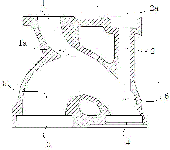
[0012] Such as figure 1 As shown, the water injection anti-backflow end cover of the water storage valve includes: a water injection pipeline 1, a water inlet pipeline 5 is arranged at the lower end of the water injection pipeline 1, and a water inlet valve 3 is arranged at the end of the water inlet pipeline 5. The water inlet pipe 5 is a bend, and under the bend mouth 1a of the water inlet pipe 5, in addition to the water inlet pipe 5, there is also a divergent water pipe 6, and the end of the divergent water pipe 6 is provided with a divergent water pipe valve. 4.

[0013] A longitudinal overflow channel 2 is arranged above the branch water pipe valve 4 .

[0014] The top end 2a of the longitudinal overflow channel 2 is a shower head.

[0015] The curved surface of the water inlet pipe 5 tends to ...


PUM


Abstract

The invention discloses a water injection backflow prevention end cover of a water storage valve. The water injection backflow prevention end cover comprises a water injection pipe, a water inlet pipe is arranged at the lower end of the water injection pipe, and a water inlet valve is arranged at the tail end of the water inlet pipe. The water inlet pipe is a bend, a water branch pipe, besides the water inlet pipe, is arranged below a bend opening of the water inlet pipe, and a water branch pipe valve is arranged at the tail end of the water branch pipe. A longitudinal overflow channel is arranged above the water branch pipe valve. The radian of the arc face of the water branch pipe is larger, so that when water pressure of input water is too large, water is injected to the water branch pipe more easily; therefore, under the condition that the water branch pipe valve is not opened, the water level of the water branch pipe rises rapidly to reach the longitudinal overflow channel; when the water pressure continues to be increased, water can overflow upwards through a shower head, and a large amount of injected water is prevented from being poured out; and a warning effect is achieved.

Description

technical field [0001] The invention relates to a water storage valve, in particular to a water filling anti-backflow end cover of the water storage valve. Background technique [0002] Now many places have installed deluge alarm valves. The current deluge alarm valves have the following problems. After the water supply system is overhauled and the water is cut off, the deluge alarm valve must be re-operated on site to make it stand up again. In metallurgy, electric power , chemical industry, traffic tunnel, papermaking and other large-scale protection areas, and places where fire water sources are shared, maintenance is troublesome, and misoperations often occur, causing undue economic losses. Moreover, the deluge alarm valve in some places has not been used for a long time, and even the deluge alarm valve in some places has not been used since it was installed at the beginning. Such a deluge alarm valve has certain hidden safety hazards. When it comes, whether the deluge ...

Claims


Application Information

Patent Timeline
Patent Type & Authority Applications(China)
IPC IPC(8): F16K27/12
Inventor 全爱军
Owner 全爱军
Why Eureka
Try Eureka