Shield tunneling machine and method for controlling same

A technology of shield machine and control valve, which is applied in the direction of earthwork drilling, mining equipment, tunnels, etc., which can solve problems such as inability to discharge slag, difficulty in discharging slag liquid in excavation bins, and affecting construction efficiency, and achieve the effect of preventing gushing

Active Publication Date: 2016-12-14
CHINA RAILWAY CONSTR HEAVY IND
View PDF5 Cites 4 Cited by
  • Summary
  • Abstract
  • Description
  • Claims
  • Application Information

AI Technical Summary

Problems solved by technology

Especially when the construction is converted into slurry mode, since the screw conveyor is usually arranged at the bottom of the shield body, the slurry discharge pipeline can only be arranged in the middle and lower part of the shield body, and it is difficult to discharge the slag liqui

Method used


Image

  • Shield tunneling machine and method for controlling same
  • Shield tunneling machine and method for controlling same

Examples


Embodiment Construction

[0040] Embodiments of the invention are described in detail below, examples of which are illustrated in the accompanying drawings. The embodiments described below by referring to the figures are exemplary and are intended to explain the present invention and should not be construed as limiting the present invention.

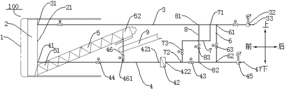
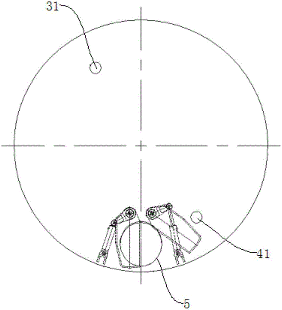
[0041] Refer below figure 1 and figure 2 A shield machine 100 according to an embodiment of the present invention is described.

[0042] Such as figure 1 and figure 2As shown, the shield machine 100 according to the embodiment of the present invention includes a cutter head 1 , a soil bin 2 , a slurry inlet pipe 3 , a slurry discharge pipe 4 , a screw conveyor 5 , a slurry discharge branch pipe 46 and a belt conveyor 9 .

[0043] Specifically, soil bin 2 is located at the rear side of cutter head 1 (as figure 1 shown rear side), the slurry inlet outlet 31 of the slurry inlet pipe 3 communicates with the soil bin 2 and is positioned at the top of the soil b...


PUM


Abstract

The invention discloses a shield tunneling machine and a method for controlling the same. The shield tunneling machine comprises a cutter head, a soil bin, a mud feed pipe, a mud discharge pipe, a spiral conveyor, a mud discharge branch pipe and a belt conveyor. The soil bin is arranged on the rear side of the cutter head; a mud feed inlet of the mud feed pipe is communicated with the soil bin and is formed in the upper portion of the soil bin; a mud discharge inlet of the mud discharge pipe is communicated with the soil bin and is formed in the lower portion of the soil bin; an input end of the spiral conveyor extends into the soil bin so that soil in the soil bin can be conveyed out of the soil bin, and the inlet end of the spiral conveyor is positioned below the mud discharge inlet; one end of the mud discharge branch pipe is communicated with an output end of the spiral conveyor, and the other end of the mud discharge branch pipe is communicated with the mud discharge pipe; an end of the belt conveyor is positioned at the output end of the spiral conveyor. The shield tunneling machine and the method have the advantage that the problem of discharge retention due to the fact that residual soil at the bottom of an existing soil bin is settled and gathered and cannot be discharged can be solved.

Description

technical field [0001] The invention relates to the technical field of tunnel construction equipment, in particular to a shield machine and a control method thereof. Background technique [0002] Generally, the type of shield machine is adapted to the geological conditions. For long-distance construction, especially when crossing strata with large geological conditions, single-mode shield machines have great limitations. In the related technology, the mud-water-soil-pressure dual-mode shield machine used adopts the coexistence mode of the screw conveyor and the mud pipeline. When the shield machine works in the earth pressure mode, the inlet and outlet pipelines are closed, and the screw conveyor and mud pipeline are used. Conveyor slag discharge, when working in muddy water mode, the screw conveyor stops working, and the slurry discharge pipeline is used to discharge slag. Especially when the construction is converted into slurry mode, since the screw conveyor is usually a...

Claims


Application Information

Patent Timeline
IPC IPC(8): E21D9/06E21D9/12
CPCE21D9/06E21D9/12
Inventor 刘飞香程永亮郑大桥何其平彭正阳罗建利陈亮张瑞临
Owner CHINA RAILWAY CONSTR HEAVY IND
Why Eureka
Try Eureka