
Laser and hard light dazzling optical device

A technology of optical device and laser light source, which is applied in the direction of offensive equipment and weapon types, etc., which can solve the problems that it is difficult to meet the requirements of long-distance high light intensity, it is difficult to warn the crowd, and it occupies a large volume.

Pending Publication Date: 2021-06-25
SHANGHAI AVIATION ELECTRIC
View PDF11 Cites 0 Cited by
  • Summary
  • Abstract
  • Description
  • Claims
  • Application Information

AI Technical Summary

Problems solved by technology

[0003] At present, the main disadvantages of the optical devices used for laser glare are: they are realized by two separate devices, the laser device and the strong light device, and occupy a large volume; the strong light devices mostly use traditional Xe light sources or LED light sources. It is difficult to meet the demand for long-distance high light intensity in a small space; most of the strong light equipment is a white light source, if wearing sunglasses can greatly prevent the impact of strong light on the human eye, it is difficult to serve the purpose of warning the crowd

Method used


Image

  • Laser and hard light dazzling optical device
  • Laser and hard light dazzling optical device
  • Laser and hard light dazzling optical device

Examples


Embodiment Construction

[0025] Embodiments of the present invention will be described in detail below, and examples of the embodiments are illustrated in the drawings, in which the same or similar reference numerals indicate the same or similar elements or components having the same or similar or similar functions. . The following is exemplary, and is intended to be used to illustrate the invention without understanding the limitation of the invention.

[0026] Since the components of the embodiments of the present invention can be implemented in a variety of ways, these directional terms are used for illustrative purposes, not the purposes of limitation. Therefore, the following detailed description is not as limited, and the scope of the invention is defined by the appended claims.

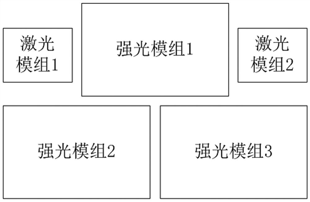
[0027] figure 1 A laser glare glare optical apparatus schematic of the present invention is schematically illustrated. The apparatus has two working modes of laser and strong light, including laser modules 1, laser module...


PUM

PropertyMeasurementUnit
wavelengthaaaaaaaaaa

Abstract

The invention discloses a laser and hard light dazzling optical device. The device has a laser working mode and a hard light working mode and comprises two laser modules and three hard light modules. In the laser working mode, the two laser modules work. In the hard light working mode, the three hard light modules and one laser module work at the same time. In other words, one laser module works in the two working modes. The laser and hard light dazzling optical device has the beneficial effects that the dazzling optical device using lasers and hard light generated through laser illumination can meet the requirements of high energy density of the lasers and high light intensity of the hard light in small space, especially, one laser module and the three hard light modules work at the same time in the hard light mode, and the non-fatal guard and warning effect can be better achieved.

Description

Technical field [0001] The present invention relates to the field of laser light and laser illumination techniques, and more particularly to a laser glare glare optical device. Background technique [0002] With the development of counter-terrorism, police non-pendant weapons are increasingly applied to counter-terrorism, assembly parade and violence, and their role is widely concerned. Acoustic, optical and electrical and electrical and electrical technology are widely used during the research and development of police non-fatal weapons. Laser glare glare devices are also increasingly valued in recent years as optical non-poisonous weapons. [0003] The drawback of optical devices currently used for laser glare glare is mainly: all of which are implemented by two discrete devices of laser devices and glare equipment devices, which takes up a large size; strong light equipment devices use traditional XE light sources or LED light sources. The smaller space is difficult to meet th...

Claims


Application Information

Patent Timeline
Patent Type & Authority Applications(China)
IPC IPC(8): F41H13/00
CPCF41H13/0056
Inventor 王立峰曾庆兵
Owner SHANGHAI AVIATION ELECTRIC
Learn More