High-power lighting lamp for centralized communication control

A lighting fixture and high-power technology, which is applied in the direction of energy-saving control technology and electrical components, can solve the problems of not being able to meet the lighting brightness of the airport driveway, not being able to realize communication signal control, and lacking fault alarm functions, so as to achieve centralized communication control and prevent Effects of interference and convenient maintenance and management

Pending Publication Date: 2021-06-22
BEIJING HANGTIAN CHANGXING S & T DEV CO LTD
View PDF7 Cites 0 Cited by
  • Summary
  • Abstract
  • Description
  • Claims
  • Application Information

AI Technical Summary

Problems solved by technology

[0002]The lighting fixtures on the existing airport bridleway are all powered by 220V mains power supply because they need to meet the work and operation requirements on the bridleway, but the existing lighting fixtures on the bridleway All are switch controlled, unable to realize centralized communication signal control and lack of fault alarm function
Although the existing intelligent evacuation emergency lighting system can realize centralized communication control of emergency lighting, the existing emergency lighting is powered by a DC power supply, and the power of the lighting is low, which cannot meet the lighting brightness on the airport driveway.

Method used


Image

  • High-power lighting lamp for centralized communication control
  • High-power lighting lamp for centralized communication control
  • High-power lighting lamp for centralized communication control

Examples


Embodiment Construction

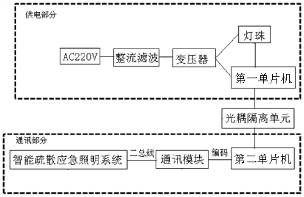
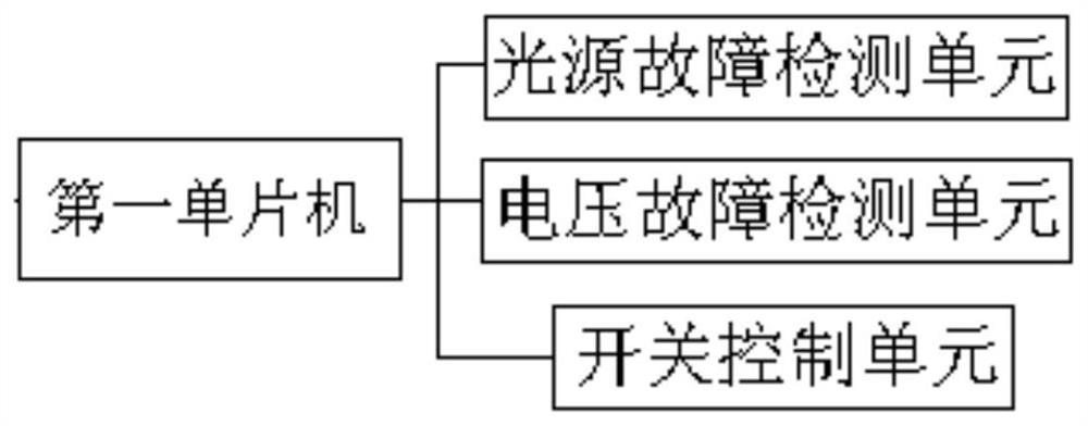
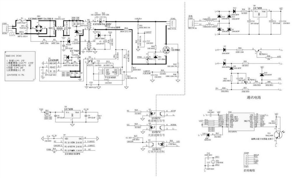
[0024] Refer to attached Figures 1 to 3 As shown, this embodiment is used for a high-power lighting fixture controlled by centralized communication, including a lamp bead, and a power supply part and a communication part connected to the lamp bead.

[0025] In this embodiment, the power supply part is directly connected to the 220V mains, and through the mains power supply, it can meet the requirements of lighting fixtures with a power of 20W and above. Of course, the power supply part can also use 220V output EPS power supply, which can also meet the needs of lighting fixtures with a power of 20W and above. The communication part is connected with the existing intelligent evacuation emergency lighting system, and provides centralized communication control for the lamp beads through the intelligent evacuation emergency lighting system.

[0026] In order to satisfy the connection between the lamp bead, the power supply part and the communication part, and prevent interference...


PUM


Abstract

The invention discloses a high-power lighting lamp for centralized communication control. The high-power lighting lamp comprises a lamp bead, and a power supply part and a communication part which are connected with the lamp bead. The power supply part is connected with a 220V alternating current, the communication part is connected with an intelligent evacuation emergency lighting system, and the power supply part and the communication part are connected through an optocoupler isolation unit. The power supply part comprises a rectifier filter, a transformer and a first single-chip microcomputer which are connected in sequence, the transformer is separately connected with the first single-chip microcomputer and the lamp bead, and the first single-chip microcomputer is connected with the optical coupler isolation unit and the lamp bead. The communication part comprises a communication module and a second single-chip microcomputer connected with the communication module, the communication module is connected with the intelligent evacuation emergency lighting system through a two-bus, and the second single-chip microcomputer is connected with the optocoupler isolation unit. According to the present invention, the dual functions of power supply and centralized communication control are achieved, the high-power illumination is achieved, the communication signal interference is prevented through the optocoupler isolation unit, the functions of fire escape, lamp fault real-time detection and accurate positioning can be achieved, and the maintenance and management are convenient.

Description

technical field [0001] The invention relates to the field of lamps, in particular to a high-power lighting lamp for centralized communication control. Background technique [0002] The lighting fixtures on the existing airport bridleway are all powered by 220V mains power supply because they need to meet the work and operation requirements on the bridleway. However, the existing lighting fixtures on the bridleway are all switch-controlled, which cannot realize centralized communication signal control and lack of faults. Alarm function. Although the existing intelligent evacuation emergency lighting system can realize centralized communication control of emergency lighting, the existing emergency lighting is powered by a DC power supply, and the power of the lighting is low, which cannot meet the lighting brightness on the airport driveway. [0003] In order to meet the power requirements of lighting fixtures on the airport driveway and the needs of centralized communication...

Claims


Application Information

Patent Timeline
IPC IPC(8): H05B47/10H05B47/175H05B47/20H05B45/00H05B45/50
CPCH05B47/10H05B47/175H05B47/20H05B45/00H05B45/50Y02B20/40
Inventor 于良海
Owner BEIJING HANGTIAN CHANGXING S & T DEV CO LTD
Why Eureka
Try Eureka