
Water flow power generation automatic thermostatic controller

A constant temperature controller and water flow power generation technology, which is applied to engine components, sliding valves, valve details, etc., can solve the problems of not being able to pass water directly, not being able to use water, and high replacement frequency, so as to achieve expanded use range and performance, simple adjustment, The effect of improving safety performance

Active Publication Date: 2018-12-07
NINGBO FEIYU GRP CO LTD
View PDF3 Cites 0 Cited by
  • Summary
  • Abstract
  • Description
  • Claims
  • Application Information

AI Technical Summary

Problems solved by technology

However, such a thermostat controller cannot be directly connected to water when the power is cut off or there is a problem with the power supply, resulting in the inability to use water.
[0004] Moreover, general thermostat controllers are usually used in conjunction with water heaters. In order to facilitate temperature adjustment, thermostat controllers are usually installed in the bathroom or near the faucet in the kitchen, that is, closer to the water outlet position. In order to adjust the water temperature and flow, the thermostat controller must be To use electricity, if you use dry batteries, the frequency of replacement is high, and there will be corrosion and leakage when in contact with water for a long time. If you directly connect to the power supply, it will make it even more unsafe to use
Therefore, at present, there has not been a constant temperature electric water heater system that is safe to use and easy to adjust for thermal storage electric water heaters.

Method used


Image

  • Water flow power generation automatic thermostatic controller
  • Water flow power generation automatic thermostatic controller
  • Water flow power generation automatic thermostatic controller

Examples


Embodiment Construction

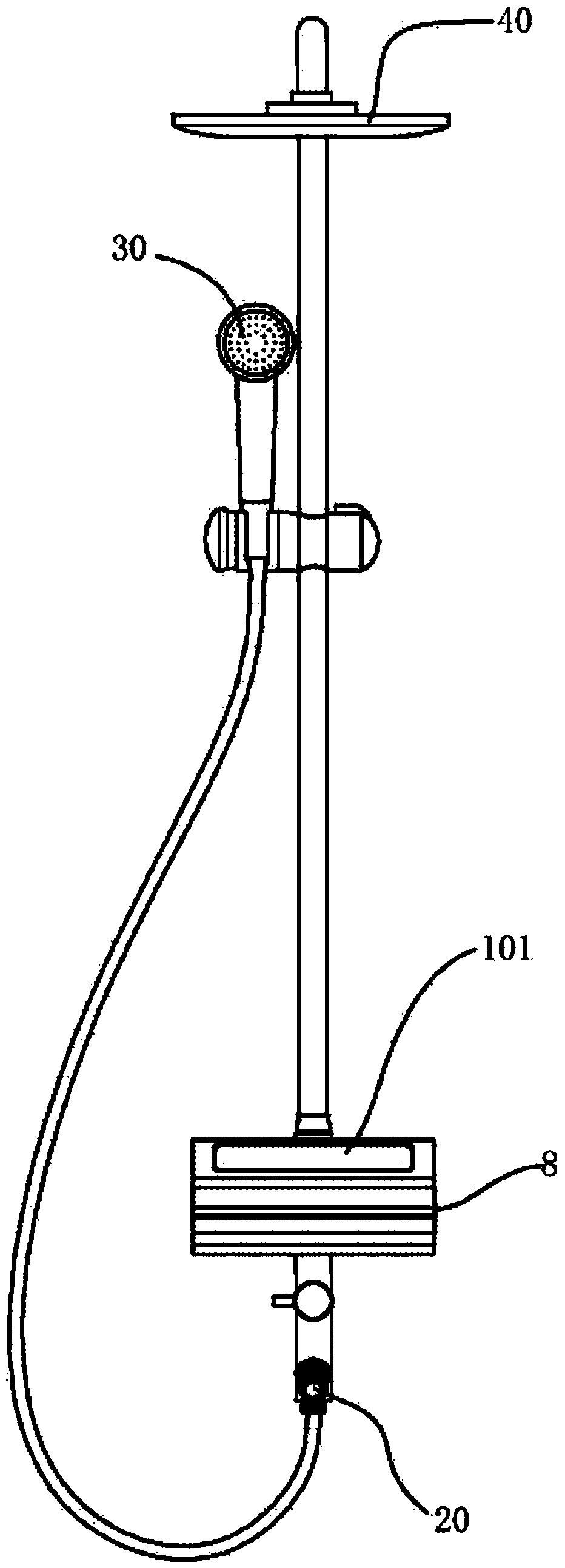
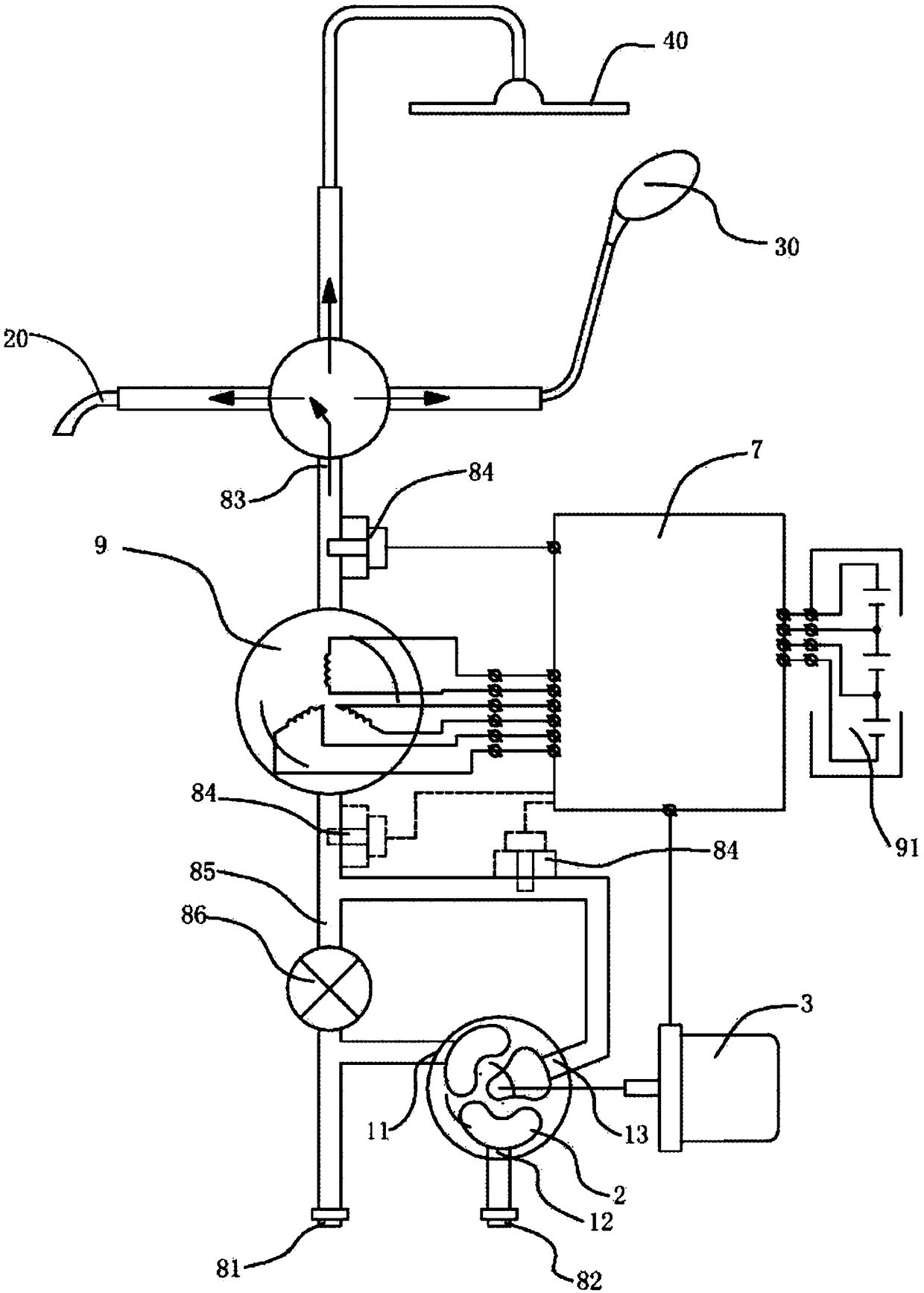
[0030] The present invention will be further described in detail below in conjunction with the accompanying drawings and embodiments.

[0031] Such as Figure 1-2 As mentioned above, the automatic constant temperature controller for water flow power generation in the embodiment of the present invention includes a housing 8 and an electric thermostatic mixing valve located in the housing 8. The electric thermostatic mixing valve includes a valve body 1 and a valve core located in the valve body 1. 2, and the driving motor 3 connected with the spool 2 and driving the spool 2 to regulate hot and cold water. The shell 8 is respectively provided with a cold water connector 81, a hot water connector 82, and a water outlet connector 83. The cold water connector 81 is connected to the external cold water pipe, and the hot water connector 82 is connected to the external hot water pipe, that is, connected to an electric water heater or a gas water heater. , the water outlet joint 83 is...


PUM


Abstract

The invention discloses a water flow power generation automatic thermostatic controller which comprises an electric thermostatic water mixing valve. The electric thermostatic water mixing valve comprises a valve element (2) and a driving motor (3) which drives the valve element (2) to move so as to adjust the water temperature. A water flow power generation device (9) is arranged between a mixed water outlet (13) of the electric thermostatic water mixing valve and a water outlet connector (83) connected with an external water drainage device, and the water flow power generation device (9) supplies power to a storage battery (91) through a control circuit module (7). The water flow power generation automatic thermostatic controller further comprises an auxiliary water pipe (85) capable of communicating with the water flow power generation device (9), and the auxiliary water pipe (85) can communicate with the water outlet connector (83) through the water flow power generation device (9).By means of the water flow power generation automatic thermostatic controller, water flow power generation can be carried out, power is supplied to the system, the drained water temperature of a water heater can be automatically adjusted, and cold water or hot water can be used in a power failure stage.

Description

technical field [0001] The invention relates to an electric water heater system. Background technique [0002] The constant temperature water heaters currently on the market are generally instant electric water heaters. The water storage electric water heater and the hot water supply system do not have the function of constant temperature and constant flow. The heat storage electric water heater usually needs to adjust the outlet water temperature through a water mixing valve. , the cold water that is about to enter and the heat in the tank are combined in a certain proportion in the water mixing valve to adjust the appropriate outlet water temperature. This water mixing process is usually manually adjusted. This adjustment method has certain defects. The hot water in the inner tank of the water heater will gradually decrease during use, so the temperature of the mixed water will also gradually decrease accordingly. Therefore, continuous adjustment is required. The mobile p...

Claims


Application Information

Patent Timeline
Patent Type & Authority Applications(China)
IPC IPC(8): F16K31/04F16K37/00F16K11/06
CPCF16K3/314F16K11/06F16K11/074F16K31/046F16K31/05F16K37/005
Inventor 陈非
Owner NINGBO FEIYU GRP CO LTD
Learn More