
Supporting frame convenient for moving display

A display and horizontal plate technology, applied in the computer field, can solve the problems of inconvenient push-pull movement of the display, wear and tear of the table, etc., and achieve the effects of simple production, improved efficiency, and reasonable design.

Active Publication Date: 2018-12-07
江苏慧学堂系统工程有限公司
View PDF0 Cites 0 Cited by
  • Summary
  • Abstract
  • Description
  • Claims
  • Application Information

AI Technical Summary

Problems solved by technology

It is a display tool that displays a certain electronic file on the screen through a specific transmission device and then reflects it to the human eye. The display is an important interactive device for people to use the computer. The computer can be intuitively operated and controlled through the display. Put the monitor on the chair and use it on the table. During long-term use, it is necessary to constantly adjust the sitting posture. When people lean back against the backrest, they need to pull the monitor to the front for easy viewing. When people sit forward and straight It is necessary to push the display to the back and keep a certain distance from the glasses. The existing display is not convenient to push and pull, and it is easy to wear and damage the table. Therefore, it is necessary to design a bracket to facilitate the movement of the display to meet the needs of use.

Method used


Image

  • Supporting frame convenient for moving display
  • Supporting frame convenient for moving display
  • Supporting frame convenient for moving display

Examples


Embodiment Construction

[0018] Below in conjunction with accompanying drawing and specific embodiment the present invention is described in further detail:

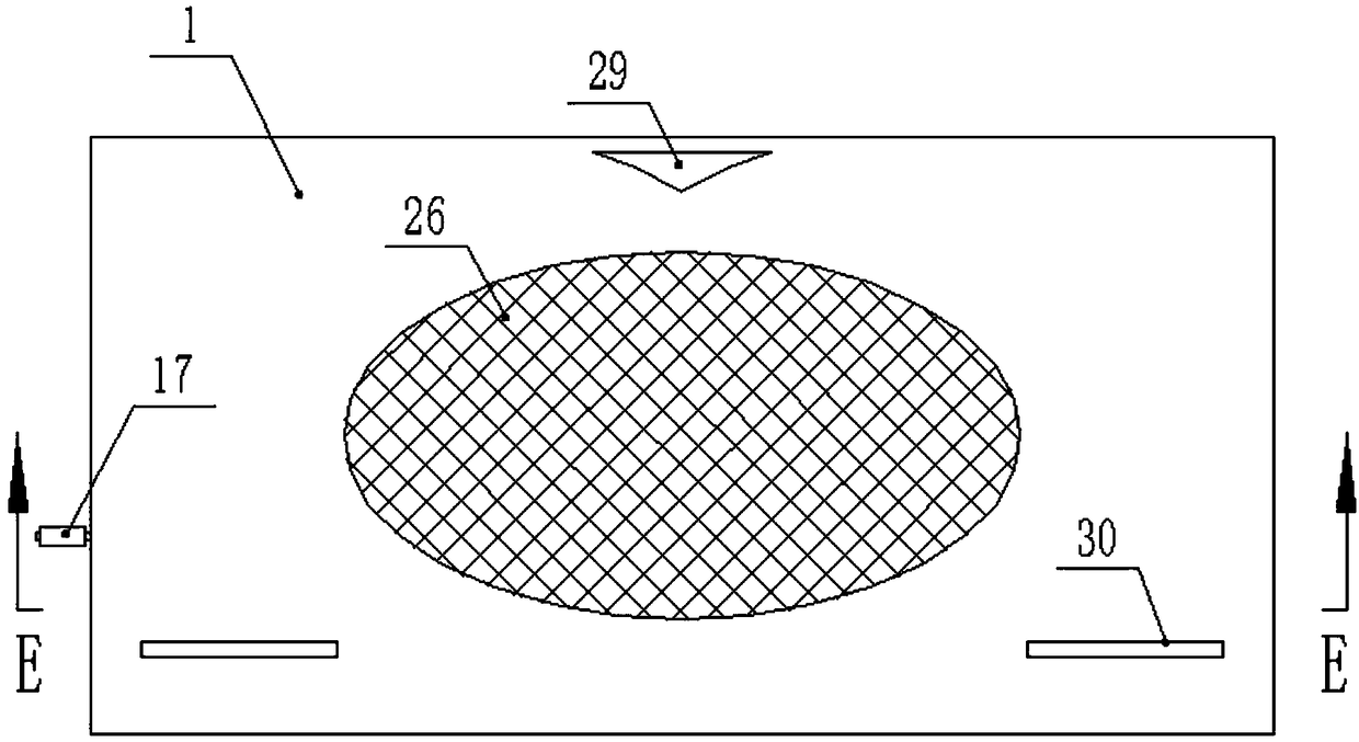
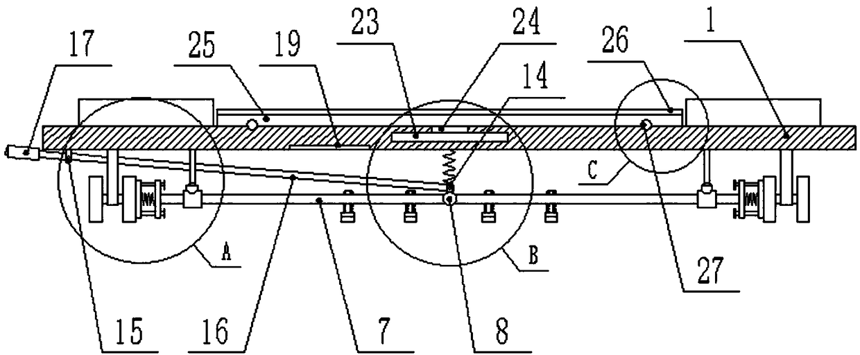
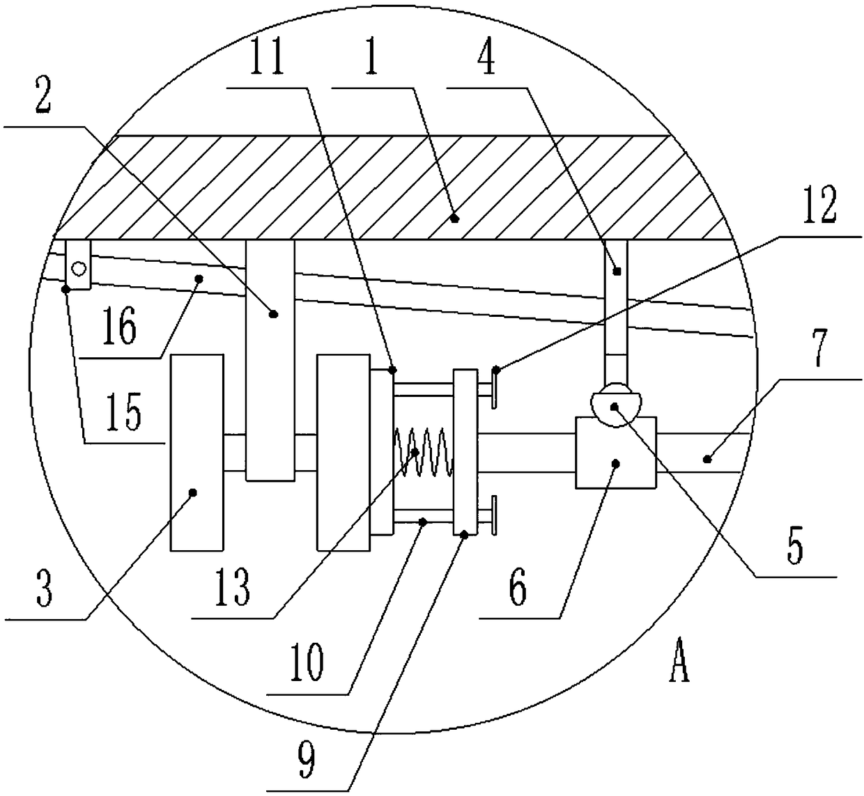
[0019] Such as figure 1 , figure 2 , image 3 , Figure 4 , Figure 5 As shown, a support for moving the display is convenient, including a horizontal plate 1, vertical bars 2 are vertically fixed at the four corners of the bottom surface of the horizontal plate 1, the lower end of the vertical bar 2 is provided with a roller 3 connected to it in rotation, and the vertical bar 2 is provided with Two fixed rods 4 vertically fixed to the horizontal plate 1, the bottom of the fixed rod 4 is fixedly equipped with a universal joint 5, and the bottom of the universal joint 5 is horizontally fixed with a sleeve 6, and a sleeve 6 is inserted into the sleeve 6 for sliding connection with it. The cross bar 7, the cross bar 7 at both ends is hinged with the central axis 8 respectively, the other end of the said cross bar 7 is provided with a positioni...


PUM


Abstract

The invention discloses a supporting frame convenient for moving a display. The supporting frame comprises a transverse plate, vertical rods are vertically fixed in the four corners of the bottom surface of the transverse plate, rollers which are rotationally connected with the vertical rods are arranged at the lower end of the vertical rods, two fixed rods which are vertically fixed with the transverse plate are arranged between the vertical rods, a universal joint is fixedly arranged at the bottom of each of the fixed rods, a sleeve is horizontally fixed at the bottom of the universal joint,transverse rods which are in sliding connection with the sleeve are inserted into the sleeve, the transverse rods at the two ends are hinged to the middle shaft separately, positioning plates fixedlyconnected with the transverse rods are arranged at the other end of the transverse rods, positioning rods slidably connected with the positioning plates are horizontally inserted into the same, the number of the positioning rods are two, pressing plates attached to the positioning rods are fixed on one side, close to the roller, of the positioning rod, and the other end of the positioning rods are fixedly provided with check rings for preventing the positioning rods from falling off.The display is pushed and pulled back and forth through the roller which is simple, convenient, fast and efficient, the table and the display cannot be worn during pushing and pulling so that the table and the display can be prevented from being damaged, the display can be rotated leftwards and rightwards through a rotating top plate which is flexible and convenient to use.

Description

technical field [0001] The invention relates to the field of computers, in particular to a support for moving a display. Background technique [0002] A display is also commonly referred to as a monitor. The display is an I / O device belonging to the computer, that is, an input and output device. It is a display tool that displays a certain electronic file on the screen through a specific transmission device and then reflects it to the human eye. The display is an important interactive device for people to use the computer. The computer can be intuitively operated and controlled through the display. Put the monitor on the chair and use it on the table. During long-term use, it is necessary to constantly adjust the sitting posture. When people lean back against the backrest, they need to pull the monitor to the front for easy viewing. When people sit forward and straight It is necessary to push the display to the rear to keep a certain distance from the glasses. The existing...

Claims


Application Information

Patent Timeline
Patent Type & Authority Applications(China)
IPC IPC(8): F16M3/00
CPCF16M3/00F16M2200/024F16M2200/08
Inventor 王红林
Owner 江苏慧学堂系统工程有限公司
Learn More