Electricity taking device and lamp provided with same

A technology for a power taking device and a lamp, which is applied to the parts, lighting device, circuit layout and other directions of the lighting device, can solve the problems of inconvenient single-person operation, inability to completely prevent mosquitoes, poor installation and controllability, etc., and achieves a simple structure. Reliable, convenient access, sealing effect

Pending Publication Date: 2018-12-07
宁波公牛光电科技有限公司
View PDF6 Cites 0 Cited by
  • Summary
  • Abstract
  • Description
  • Claims
  • Application Information

AI Technical Summary

Problems solved by technology

The main disadvantage of using this method is that the installation is not convenient and there is a certain risk of electric shock
It is inconvenient for one person to operate, and the installation control is poor, it is time-consuming and laborious, it cannot completely prevent mosquitoes, and it is not easy to disassemble for daily cleaning

Method used


Image

  • Electricity taking device and lamp provided with same
  • Electricity taking device and lamp provided with same
  • Electricity taking device and lamp provided with same

Examples


Embodiment Construction

[0063] In order to make it easy to understand the technical means, creative features, goals and effects achieved by the present invention, the following embodiments are combined with the accompanying drawings to illustrate the details provided by the present invention.

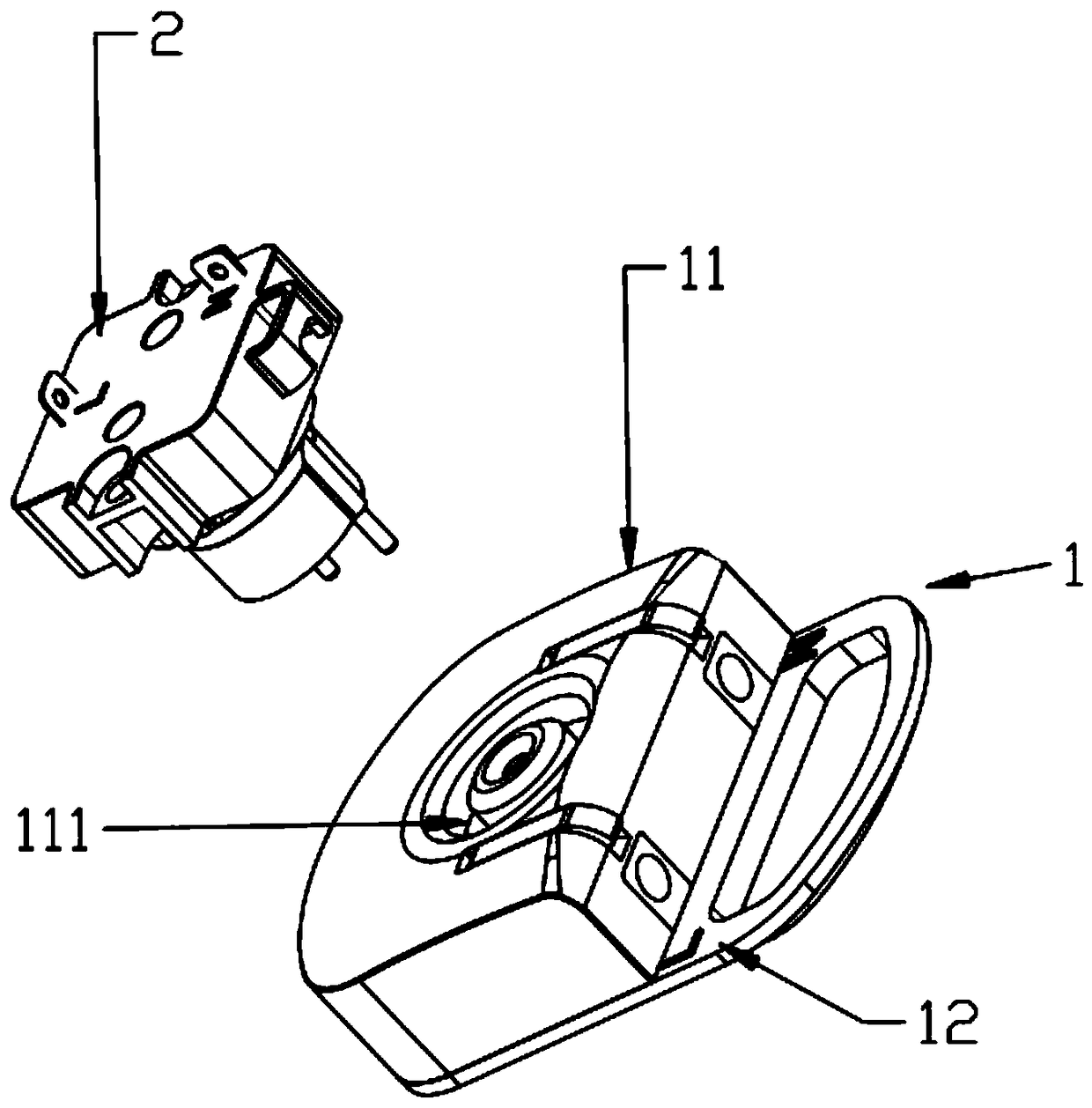
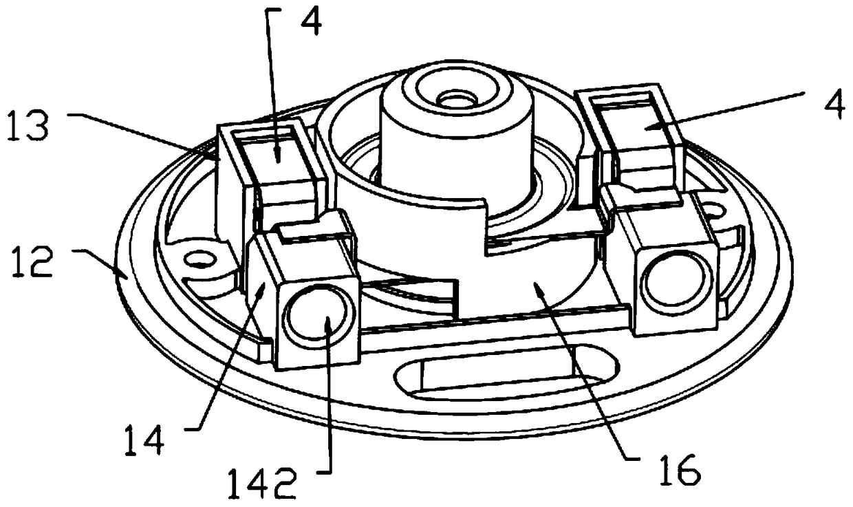
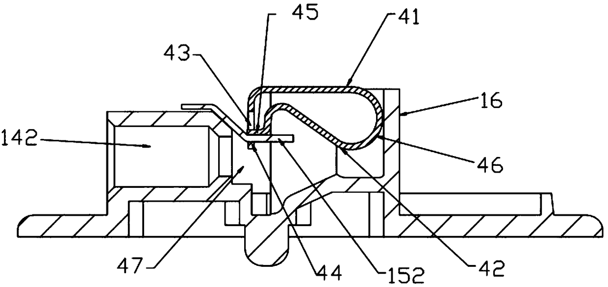
[0064] figure 1 It is a schematic diagram of the structure of the power taking device of the present invention; figure 2 It is a schematic diagram of the internal structure of the female terminal in the power taking device of the present invention. See figure 1 with figure 2 As shown, a preferred power-taking device is shown, which includes a male end 2 and a female end 1 that are plugged into each other. The female end 1 is provided with a accommodating cavity that can accommodate the male end 2. The plug is inserted; the female end also includes a first conductive portion and a trigger portion. Wherein, the first conductive part includes one-to-one corresponding conductive parts and wire clip 4, at least two ...


PUM


Abstract

The invention discloses an electricity taking device and a lamp provided with the same. The electricity taking device comprises a male end and a female end connected to each other in a plugged manner.The female end comprises a first electric conduction part which comprises at least two electric conduction pieces and wire clamping elastic pieces in one-to-one correspondence, the number of poles and groups of plugs are same, and the plugging region of each electric conduction piece is inserted into the corresponding wire clamping elastic piece and is matched with the wire clamping elastic pieceto form a clamping port; each electric conduction piece is provided with an electric conduction piece is provided with an electric conduction region electrically connected to the inserted plug, and the electric conduction region of each electric conduction piece is electrically connected to one pole of the plug correspondingly; and the electricity taking device also comprises triggering parts matched with or connected to the wire clamping elastic pieces for controlling the sizes of the clamping ports. According to the electricity taking device disclosed by the invention, the male end and thefemale end lean against each other rotatably and are externally connected to a lampshade, and the lampshade needs not to be detached. Meanwhile, the electricity taking device needs not to be mounted in an aligned manner, so that the electricity taking device is more conveniently mounted and detached. The triggering parts are matched with the wire clamping elastic pieces to control the sizes of theclamping ports, so that external wires are connected and clamped conveniently.

Description

Technical field [0001] The present invention relates to the technical field of lamps, in particular to a power-taking device and a lamp with the device. Background technique [0002] When installing ceiling lamps on the market, the lampshade and the lamp body need to be separated. The lamp body is equipped with screw-fixed terminal blocks. Fix the mains neutral wire and live wire with screws respectively. This kind of fixed terminal is generally designed in the lamp body, the lamp cover needs to be opened, and a fixing screw tool is also needed to fix the wiring. The main disadvantage of this method is that the installation is not convenient and there is a certain risk of electric shock. It is inconvenient for one-person operation, poor installation and controllability, time-consuming and laborious, not completely mosquito-proof, and difficult to disassemble for daily cleaning. Summary of the invention [0003] In view of the above-mentioned problems in the prior art, the aim i...

Claims


Application Information

Patent Timeline
Patent Type & Authority Applications(China)
IPC IPC(8): F21S8/00F21S8/04F21V17/16F21V23/06
CPCF21S8/00F21S8/04F21V17/16F21V23/06
Inventor 雷清元
Owner 宁波公牛光电科技有限公司
Why Eureka
Try Eureka