
Non-full-tube flow calibration device

A calibration device and a non-full pipe technology, which is applied in the direction of test/calibration device, measurement device, liquid/fluid solid measurement, etc., can solve the problems of increasing the operation amount of construction personnel and complicated calibration methods of open channel flowmeters

Active Publication Date: 2018-12-07
浙江清环智慧科技有限公司 +1
View PDF5 Cites 1 Cited by
  • Summary
  • Abstract
  • Description
  • Claims
  • Application Information

AI Technical Summary

Problems solved by technology

[0005] The purpose of the present invention is to provide a non-full pipe flow calibration device to solve the technical problems in the prior art that the calibration method of the open channel flowmeter is complicated and the operation amount of the construction personnel is increased.

Method used


Image

  • Non-full-tube flow calibration device
  • Non-full-tube flow calibration device
  • Non-full-tube flow calibration device

Examples


Embodiment Construction

[0027] The technical solutions of the present invention will be clearly and completely described below in conjunction with the accompanying drawings. Apparently, the described embodiments are some of the embodiments of the present invention, but not all of them. Based on the embodiments of the present invention, all other embodiments obtained by persons of ordinary skill in the art without making creative efforts belong to the protection scope of the present invention.

[0028] In the description of the present invention, it should be noted that if the terms "center", "upper", "lower", "left", "right", "vertical", "horizontal", "inner", "outer" appear ” and other indicated orientations or positional relationships are based on the orientations or positional relationships shown in the accompanying drawings, which are only for the convenience of describing the present invention and simplifying the description, rather than indicating or implying that the referred device or element ...


PUM


Abstract

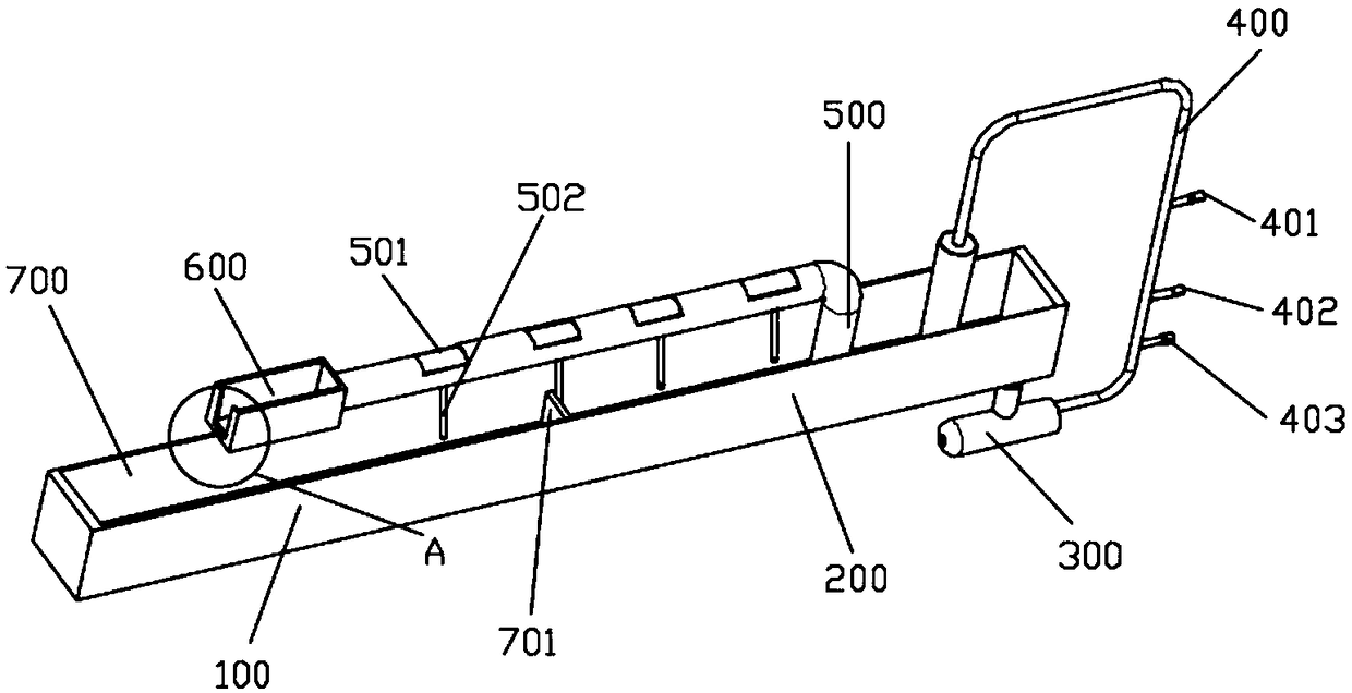
The invention provides a non-full-tube flow calibration device, and relates to the technical field of flow measurement. The non-full-tube flow calibration device comprises a first water storage tank,a second water storage tank, a water pump, a communicating pipe and a simulated non-full-tube pipeline; the first water storage tank, the water pump, the communicating pipe and the simulated non-full-tube pipeline are communicated in sequence, and a water outlet of the simulated non-full-tube pipeline is arranged corresponding to the second water storage tank; the water pump is used for controlling water output amount of the first water storage tank, the simulated non-full-tube pipeline is provided with an opening, the opening is provided with a measured flow probe, the second water storage tank is used for receiving outlet water of the simulated non-full-tube pipeline, so that recorded data of the measured flow probe is compared with the total water amount of the second water storage tank. The technical problem in the prior art that the calibration method is complicated and operated difficultly is solved. The non-full-tube flow calibration device simulates the use environment of a non-full-tube flowmeter, and the accuracy of the measured flow probe is determined by comparing the total water amount of the second water storage tank with the data of the measured flow probe.

Description

technical field [0001] The invention relates to the technical field of flow measurement, in particular to a partial pipe flow calibration device. Background technique [0002] With the development of science and technology, there is an increasing demand for liquid level monitoring in municipal and water conservancy fields such as rainwater, sewage, reclaimed water, rivers, lakes, and roads. In recent years, the country has paid more and more attention to the liquid level measurement and monitoring data of urban rivers and drainage pipes. Flow measurement is now widely used flowmeter, flowmeter variety, can be divided into rotameter, throttling flowmeter, slit flowmeter, volumetric flowmeter, electromagnetic flowmeter, ultrasonic flowmeter and so on. Many flowmeters require that the liquid in the pipeline fills the cross section of the pipeline, and the flow rate of the liquid passing through the flowmeter is obtained by different methods. However, under some specific condi...

Claims


Application Information

Patent Timeline
Patent Type & Authority Applications(China)
IPC IPC(8): G01F25/00
CPCG01F25/17
Inventor 李磊赵研锋赵冬泉
Owner 浙江清环智慧科技有限公司
Learn More