L1C/A and L1C combined capturing method and device of GPS

A joint capture and signal technology, which is applied in the field of satellite navigation and positioning, can solve problems such as miscapture, sub-peak suppression effect is not obvious, and hardware resource consumption is high, so as to avoid miscapture and missed capture, solve the problem of capture ambiguity, The effect of improving capture sensitivity

Active Publication Date: 2018-12-07
GUILIN UNIV OF ELECTRONIC TECH
View PDF5 Cites 4 Cited by
  • Summary
  • Abstract
  • Description
  • Claims
  • Application Information

AI Technical Summary

Problems solved by technology
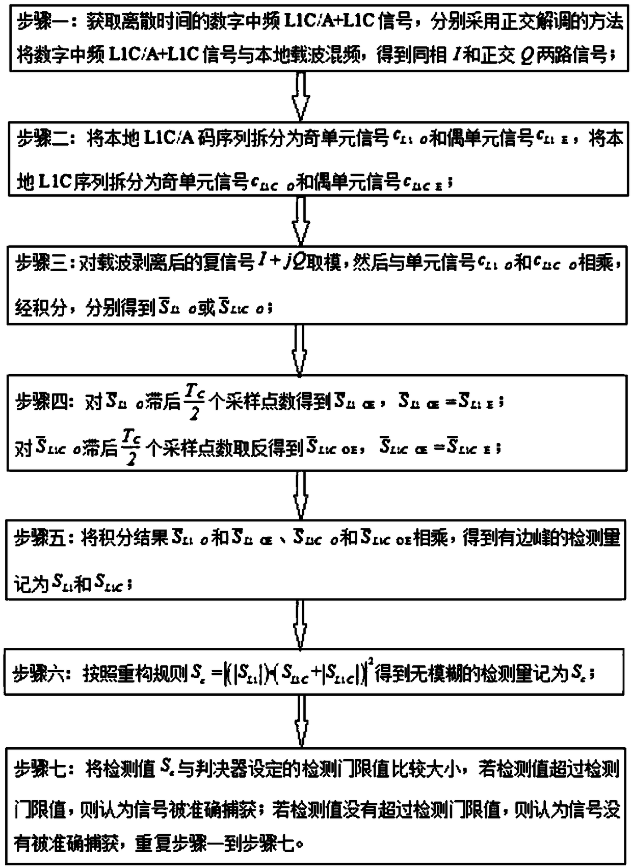
However, since the period of the L1C / A signal is 1ms, and the period of the L1C signal is 10ms, there are 9 sub-peaks in the detection quantity obtained by traditional joint capture, which may easily lead to the problem of false capture.
The traditional joint acquisition scheme includes: the joint acquisition of one or three channels, the local L1C data code, pilot code and L1C / A code are correlated with the received signal respectively, and the sum of the squares of the three channels is taken as the detection amount, which fully utilizes the signal energy, but the sub-peak suppression effect is not obvious, and the hardware resource consumption is more; 2. Single-channel joint capture, using the linear combination of C / A code, L1C pilot and data code to generate local composite code, realized in a single channel Capture saves hardware resources, and the span of the correlation peak is 1 chip, but this method still does not completely eliminate the secondary peak; 3. The dual-channel joint capture of the pilot component of L1C and the L1C / A code signal, using the coherent method , correlate the local pilot code and C / A code with the received signal respectively, and obtain a sharper detection peak, but this method wastes the energy of the L1C signal data channel, and cannot reflect the structural advantages of the new civilian L1C signal dual-channel, and There are still 9 secondary peaks, and the peak-to-peak ratio of the secondary peak to the main peak reaches 50.96%

Method used


Image

  • L1C/A and L1C combined capturing method and device of GPS
  • L1C/A and L1C combined capturing method and device of GPS
  • L1C/A and L1C combined capturing method and device of GPS

Examples


Embodiment Construction

[0054] Embodiments of the present invention are described below through specific examples, and those skilled in the art can easily understand other advantages and effects of the present invention from the content disclosed in this specification. The present invention can also be implemented or applied through other different specific implementation modes, and various modifications or changes can be made to the details in this specification based on different viewpoints and applications without departing from the spirit of the present invention. It should be noted that, in the case of no conflict, the following embodiments and features in the embodiments can be combined with each other.

[0055] It should be noted that the diagrams provided in the following embodiments are only schematically illustrating the basic ideas of the present invention, and only the components related to the present invention are shown in the diagrams rather than the number, shape and shape of the compo...


PUM


Abstract

The invention provides an L1C / A and L1C combined capturing method and device of a PGS. The method comprises that 1) digital intermediate-frequency L1C / A+L1C signals in discrete time are obtained, andin-phase I and quadrature Q paths of signals are obtained; 2) a local L1C / A code sequence is divided into an odd unit signal C<L1_0> and an even unit signal C<L1_E>, and a local L1C sequence is divided into an odd unit signal C<L1C_0> and an even unit signal C<L1C_E>; 3) a module is picked up from a carrier wave removed complex signal I+jQ, and multiplied with the unit signals C<L1_0> and C<L1C_0>, and S<L1_0><-> and S<L1C_0> <-> are obtained respectively by integration; 4) S<L1_OE><-> is obtained by lagging S<L1C_0> <-> for Tc / 2 sampling points, and S<L1C_OE><-> is obtained by lagging S<L1C_0> <-> for Tc / 2 sampling points and negating; 5) the integration results S<L1_0><-> is multiplied with S<L1_OE><-> and the integration results S<L1C_0> <-> is multiplied with the S<L1C_OE><-> to obtaindetection quantities S<L1> and S<L1C> with wings respectively; 6) an unambiguous detection quantity Sc is obtained according to the reconstruction rule Sc equals the square of an absolute value of the product of the absolute value of S<L1> and (S<L1C>+the absolute value of (S<L1C>); and 7) the detection quantity SC is compared with a detection threshold set by a decision device, if the detectionvalue exceeds the detection threshold, it is determined that the signal is captured accurately, and otherwise, it is determined that the signal is not captured accurately, and the steps 1) to 7) are repeated.

Description

technical field [0001] The invention belongs to the technical field of satellite navigation and positioning, and in particular relates to a GPS L1C / A and L1C joint acquisition method and device. Background technique [0002] Currently, the L1 frequency band is the only frequency band with two different GPS (Global Positioning System, Global Positioning System) civilian signals, that is, GPS users can receive traditional L1C / A signals and new L1C signals on the same frequency. The L1C / A signal is modulated by binary phase shift keying (BPSK). The L1C signal has a dual-channel structure of a pilot channel and a data channel. The data channel adopts BOC (1,1) modulation, and the pilot channel adopts TMBOC (6,1,4 / 33) modulation. The same-frequency L1C / A and the navigation message information modulated by the L1C signal are synchronous, and the code delay of L1C / A is the same as that of the data code and pilot code of the L1C signal. The joint acquisition of GPS L1C / A and L1C s...

Claims


Application Information

Patent Timeline
IPC IPC(8): G01S19/29G01S19/30
CPCG01S19/29G01S19/30
Inventor 孙希延郝放纪元法郝青儒符强王守华付文涛李有明甘兴利
Owner GUILIN UNIV OF ELECTRONIC TECH
Why Eureka
Try Eureka