Analysis method for dynamic aircraft motion characteristics by twin-line array TDI space camera

An analysis method and space camera technology, applied in image analysis, image data processing, instruments, etc., can solve problems such as analysis of motion characteristics, inability to perceive dynamic moving targets, and inability to determine the dynamic characteristics of targets

Active Publication Date: 2018-12-07
CHANGCHUN INST OF OPTICS FINE MECHANICS & PHYSICS CHINESE ACAD OF SCI
View PDF8 Cites 7 Cited by
  • Summary
  • Abstract
  • Description
  • Claims
  • Application Information

AI Technical Summary

Problems solved by technology

[0002] The remote sensing satellite TDI camera push-broom image is a static image, and some dynamic moving targets are also displayed in a static form in the TDI camera push-broom image, so that the dynamic characteristics of the target cannot be determined
In order to obtain the dynamic movement process of the target, the current satellite imaging adopts the staring imag...

Method used


Image

  • Analysis method for dynamic aircraft motion characteristics by twin-line array TDI space camera
  • Analysis method for dynamic aircraft motion characteristics by twin-line array TDI space camera
  • Analysis method for dynamic aircraft motion characteristics by twin-line array TDI space camera

Examples


specific Embodiment approach 1

[0036] Specific implementation mode 1. Combination Figure 1 to Figure 4 Illustrate the present embodiment, the analysis method of dynamic aircraft motion characteristic of double linear array TDI space camera, this method is realized by the following steps:

[0037] 1. Determine the positional relationship of the dual line array TDI cameras;

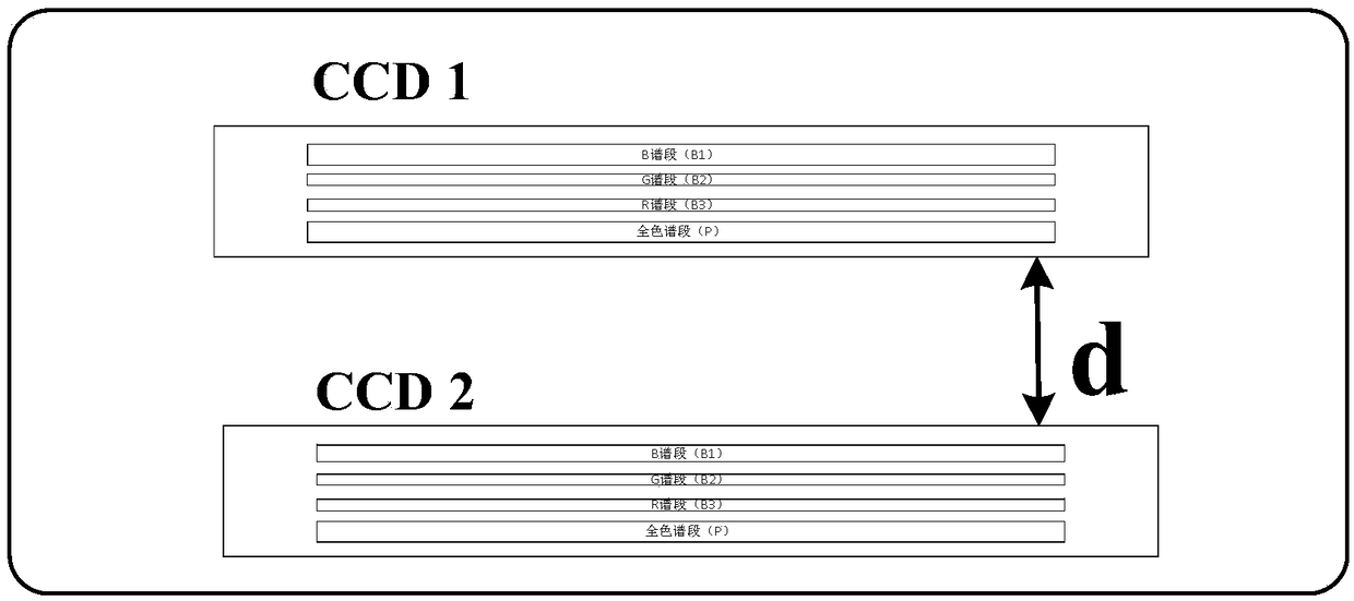
[0038] The dual linear array TDI CCD is composed of two rows of TDI CCDs that are on the same line and parallel to each other. The gap between the second row of CCDs and the first row of CCDs is as follows: figure 2 shown. The pixel size is a, and the distance between two parallel CCDs is d.

[0039] 2. Calculate the time interval of the imaging of the same target by the dual linear array TDI CCD;

[0040] The dual linear array TDI CCDs arranged in parallel on the focal plane, due to the existence of a certain distance interval, there is also a certain time interval when imaging the same target twice. The corresponding time interva...

specific Embodiment approach 2

[0062] Specific embodiment two, this embodiment is the embodiment of the method for analyzing the dynamic aircraft motion characteristics of the dual linear array TDI space camera described in the specific embodiment one:

[0063] 1. Determine the positional relationship of the dual line array TDI cameras;

[0064] The double-line array TDI CCD is composed of two rows of TDI CCDs in the same straight line and parallel to each other, the parallel distance d is 7mm, and the pixel size is a=7μm.

[0065] 2. Calculate the time interval of the imaging of the same target by the dual linear array TDI CCD;

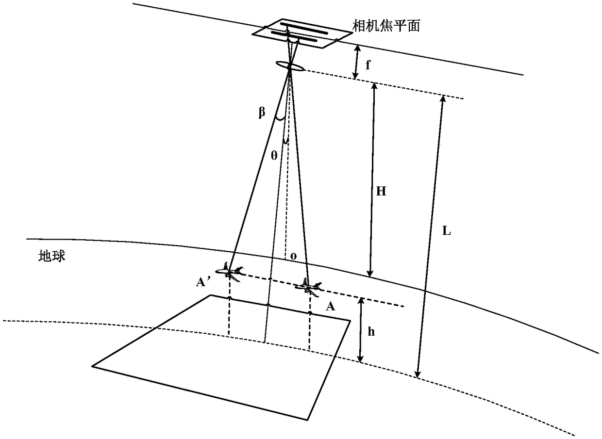
[0066] The orbital altitude of the satellite in orbit is 500km, the speed corresponding to the sub-satellite point is 7.5km / s, and the focal length of the camera is 6m; then the corresponding image surface speed is The corresponding time difference between parallel TDIs is

[0067] 3. Calculation of the center point position of the dynamic target;

[0068] Since the dual lin...


PUM


Abstract

The present invention provides an analysis method for dynamic aircraft motion characteristics by a twin-line array TDI space camera, and relates to the fields of TDI camera dynamic imaging and image processing. The technical problems of motion characteristic imaging analysis of motion targets such as an aircraft in an area of hundreds of square kilometers in the prior art are solved. The method does not change a push-broom imaging mode of a TDI camera, establishes a space optical dynamic imaging three-dimensional position and speed vector model according to the time and space information association of push-broom imaging between the dynamic change target of space flight and the twin-line array TDI camera, employs a median method to calculate a dynamic flight geometric center as a positionmiss distance, and finally employs speed vector mapping to calculate the flight speed and direction of the dynamic target to achieve motion characteristic imaging analysis of the dynamic targets suchas an aircraft. The analysis method for dynamic aircraft motion characteristics by the twin-line array TDI space camera is simple, reliable and easy to implement, and can perform analysis for the motion characteristics of large-range dynamic targets through short-interval static images to allow the dynamic motion target position and the time information to strictly maintain matching.

Description

technical field [0001] The invention relates to the field of dynamic imaging and image processing of a TDI camera, in particular to a method for analyzing dynamic aircraft motion characteristics of a double-line array TDI space camera. Background technique [0002] The remote sensing satellite TDI camera push-broom image is a static image, and some dynamic moving targets are also displayed in a static form in the TDI camera push-broom image, so the dynamic characteristics of the target cannot be determined. In order to obtain the dynamic movement process of the target, the current satellite imaging adopts the staring imaging mode. The field of view is small, mainly concentrated in a range of more than ten square kilometers, while the active areas of moving targets such as aircraft are mostly concentrated in areas of hundreds of square kilometers. The conventional staring imaging mode cannot perceive dynamic moving targets in a wide space range. And analyze the motion charac...

Claims


Application Information

Patent Timeline
IPC IPC(8): G06T7/292
CPCG06T2207/10032G06T7/292
Inventor 杨秀彬朱琳王旻徐超徐婷婷
Owner CHANGCHUN INST OF OPTICS FINE MECHANICS & PHYSICS CHINESE ACAD OF SCI
Why Eureka
Try Eureka