Leakage protector

A technology of leakage protector and protector, which is applied in protection switch, emergency protection device, parts of protection switch, etc., can solve problems such as circuit breaker of leakage protector, achieve high reliability, enhance safety performance, and improve safety Effect

Pending Publication Date: 2018-12-07
YUYAO JIARONG ELECTRONICS & ELECTRIC APPLIANCE CO LTD
View PDF1 Cites 1 Cited by
  • Summary
  • Abstract
  • Description
  • Claims
  • Application Information

AI Technical Summary

Problems solved by technology

[0005] In view of the above-mentioned defects in the prior art, the present invention provides a leakage protector, which solves the problem that the leakage protector can only be disconnected when it is powered on.

Method used


Image

  • Leakage protector
  • Leakage protector
  • Leakage protector

Examples


Embodiment 1

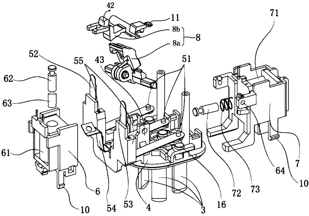
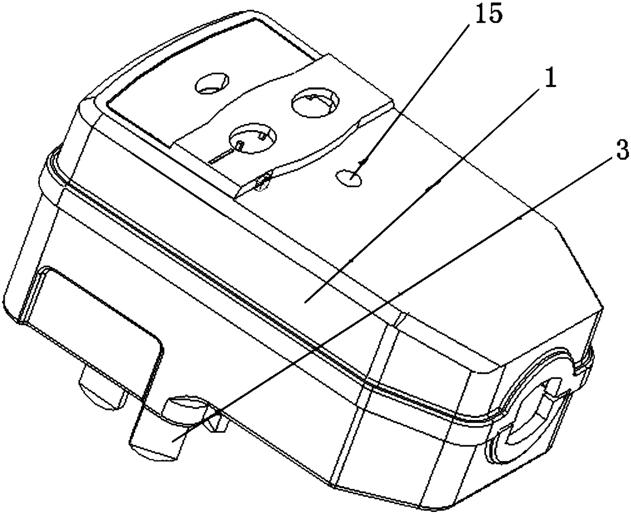
[0043] A leakage protector according to an embodiment of the present invention, such as figure 1 with figure 2 As shown, it includes: protector shell 1, protector device 2, pin 3, bottom plate 4 and shrapnel 5, protector device 2 is set on the upper part of bottom plate 4, protector device 2 controls the opening and closing of leakage protector, and pin 3 is set at the lower part of the bottom plate 4;

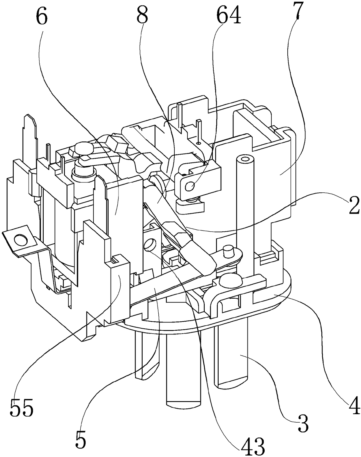
[0044] The protector device 2 includes a communication maintenance device 6, a communication device 7 and a locking device 8, the locking device 8 is arranged between the communication maintenance device 6 and the communication device 7 and is used to control the opening and closing of the shrapnel 5 and the pin 3;

[0045] The locking device 8 includes a shrapnel pressing block 8a and a locking lever 8b. The locking lever 8b is articulated with the second bearing 64 provided on the communication device 7 through the second pin shaft 31. The shrapnel pressing block 8a passes...

Embodiment 2

[0063] Such as Figure 9 As shown, compared with Embodiment 1, the elastic piece 5 includes a first elastic piece 52 and a second elastic piece 53, and the first elastic piece 52 and the second elastic piece 53 are fixed by the elastic piece slots 55 arranged on both sides of the communication maintenance device 6; The top of the pin 3 is provided with an electrical connection contact 16, and the ends of the first elastic piece 52 and the second elastic piece 53 are provided with an elastic contact 51 corresponding to the electrical connection contact 16. When the pressing rod 22 presses down the elastic piece 5, The shrapnel contact 51 is in contact with the electrical connection contact 16; in this embodiment, the first shrapnel 52 and the second shrapnel 53 correspond to the live wire pin and the neutral wire pin respectively, and the PE line cannot be disconnected, and in this embodiment, remove The setting of the PE wire shrapnel 54 communicates the PE wire pins with the ...

Embodiment 3

[0065] Such as Figure 7 with Figure 8 As shown, compared with Embodiment 1, a pre-hinge device is provided on the hinge seat, and the pre-hinge device includes a boss 13 and a locking groove 14. The boss 13 is located at the hinge of the upper part 8c of the pressing block, and the locking groove 14 Located at the hinge of the lower part 8d of the pressing block, through the cooperation of the boss 13 and the engaging groove 14, the pre-hinging of the upper part 8c of the pressing block and the lower part 8d of the pressing block is realized, that is, when the first pin shaft 21 is not installed, it can also be The installation of the shrapnel pressing block 8a is completed, and at the same time, the design can further ensure the coaxiality between the upper part 8c of the pressing block and the lower part 8d of the pressing block, which can reduce wear and tear, and the overall installation is simpler and more convenient.


PUM


Abstract

The invention, which relates to the technical field of electrical equipment protection, discloses a leakage protector comprising a protector device, pins, a bottom plate and an elastic piece. The protector device includes a communication maintaining device, a communicating device and a locking device. The locking device includes an elastic piece pressing block and a locking lifting lever; a lock catch, a transverse fork groove and a buckle sliding way are arranged at the locking lifting lever; and a pressing rod, a buckle and a vertical fork groove are arranged at the elastic piece pressing block. A second iron core extending horizontally is arranged at the communicating device and is in a clamping fit relationship with the vertical fork groove. A first iron core extending longitudinally is arranged at the communication maintaining device and is in a clamping fit relationship with the horizontal fork groove. The elastic piece pressing block includes an upper pressing block part and a lower pressing block part. According to the invention, disconnection of the leakage protector is realized based on the cooperation relationship between mechanical structures under the circumstance thatthe failure of the coil is kept. With pressing block springs, a pressing rod arranged at the lower pressing block part applies a stable compression force to the elastic piece; and with a compressiontop block, the first iron core can move to a lowest position.

Description

technical field [0001] The invention relates to the technical field of electrical equipment protection, in particular to a leakage protector. Background technique [0002] The leakage protector can disconnect the main line in time when the equipment has a leakage fault or needs to protect the personal electric shock with fatal danger, so it is widely used; the leakage protector is mainly used when the equipment has a leakage fault and For personal electric shock protection with fatal danger, it has overload and short-circuit protection functions, which can be used to protect the overload and short-circuit of the circuit or motor, and can also be used for infrequent switching and starting of the circuit under normal conditions; the existing leakage protector is in the If there is a power failure in the working state, the leakage protector is still in the closed state, and the leakage protector can only be disconnected when the power is turned on. [0003] As disclosed in Chi...

Claims


Application Information

Patent Timeline
IPC IPC(8): H01H71/12H01H71/24
CPCH01H71/121H01H71/2481
Inventor 钱加灿
Owner YUYAO JIARONG ELECTRONICS & ELECTRIC APPLIANCE CO LTD
Why Eureka
Try Eureka